| |
| PIR Sensor with mounted Fresnel Lens |
A PIR module is basically made of a pyroelectric sensor (see it below as the round metal can with a rectangular crystal in the center), which can detect levels of infrared radiation. Everything emits some low level radiation, and the hotter something is, the more radiation is emitted. The sensor in a motion detector is actually split in two halves. The reason for that is that we are looking to detect motion (change) not average IR levels. The two halves are wired up so that they cancel each other out. If one half sees more or less IR radiation than the other, the output will swing high or low.
 |
| PIR Sensor uncovered |
Along with the pyroelectic sensor is a bunch of supporting circuitry,
resistors and capacitors. It seems that most small hobbyist sensors use
the Micro Power PIR Motion Detector IC BISS0001 . This chip takes the output of the
sensor and does some minor processing on it to emit a digital output
pulse from the analog sensor.
 | |
| Bottom Side |
 |
| Micro Power PIR Motion Detector IC |
In PIR module description you can find that it's powered at 5V! And as you know already ESP8266 it's a 3V only chip. This thing can be a joy-breaker.
The good thing is that if you look in the BISS0001 datasheet you will see that it's working ok also at 3V level. So maybe we are lucky today.
Looking deeper on the PIR Module board we can find even better news: The board it's actually already a 3V one! The 5V voltage from the power pin is going only to the onboard power regulator! Output is at 3V logic levels. No level shifting or anything else needed ! Neat!
 |
| Holtek 3.3V LDO power regulator |
This give us 2 options for powering it up: using the existing 5V pin or if you want to use it in a 3V only setup, just bypass or remove the regulator and that's it.
Connecting the PIR sensor module is pretty trivial, as it has only 3 PIN: GND, DOUT and VCC. The PIR
acts as a digital output so all you need to do is listen for the pin status change to HIGH (motion detected) or LOW (no motion detected).
What we will need:
- CBDB Board
- USB adapter (take a look on Part 1 for details how to connect them together)
- PIR Module from above
- LED module x 2
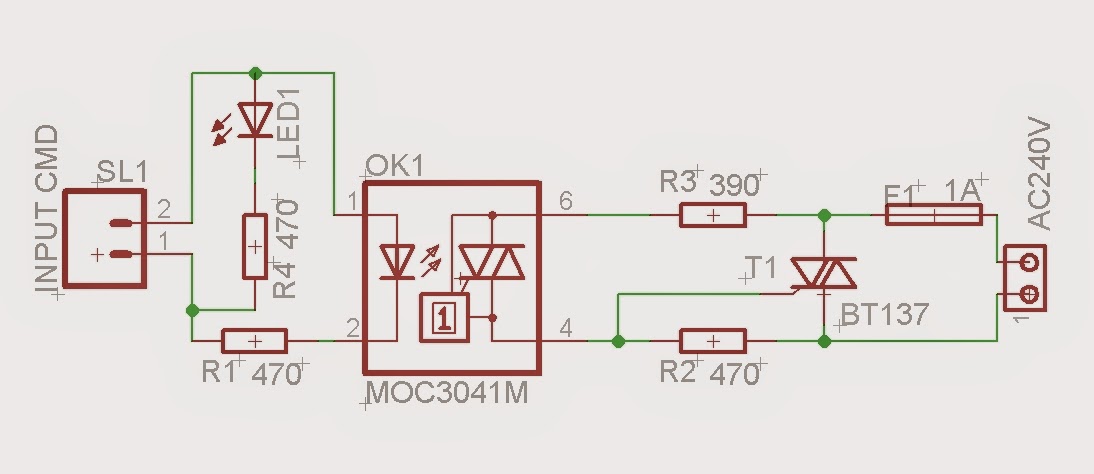
- Main power switch module

For programming CBDB Board and uploading the driver and the software we will continue to use the LuaUploader as before.
First test program: Blink a LED when movement detected
 |
| PIR "Blinky" running |
1. Initialise used PINs:
outpin=3 -- Select output pin - GPIO0
gpio.mode(outpin,gpio.OUTPUT)
inpin=6 -- Select input pin - GPIO12
gpio.mode(inpin,gpio.INT,gpio.PULLUP) -- attach interrupt to inpin
gpio.mode(outpin,gpio.OUTPUT)
inpin=6 -- Select input pin - GPIO12
gpio.mode(inpin,gpio.INT,gpio.PULLUP) -- attach interrupt to inpin
2. Motion Detection function - called by the trigger on rising edge
function motion()
print("Motion Detected!")
gpio.write(outpin,gpio.HIGH) -- Led ON - Motion detected
tmr.delay(5000000) -- delay time for marking the movement
gpio.write(outpin,gpio.LOW) -- Led OFF
end
3. Trigger INPIN on rising edge - based on internal interrupt mechanism
print("Motion Detected!")
gpio.write(outpin,gpio.HIGH) -- Led ON - Motion detected
tmr.delay(5000000) -- delay time for marking the movement
gpio.write(outpin,gpio.LOW) -- Led OFF
end
3. Trigger INPIN on rising edge - based on internal interrupt mechanism
gpio.trig(6,"up",motion)
Save the code on ESP as 'pir.lua', restart ESP and run:
dofile(pir.lua") -- Start PIR Program

First Test video:
Example 2: Web enabled PIR Motion detection
To be able to see online the PIR sensor status we will add a Web Server component to our program
2.1. Web Server
srv=net.createServer(net.TCP)
srv:listen(80,
function(conn)
conn:on("receive",function(conn,payload) print(payload)
conn:send("HTTP/1.1 200 OK\n\n")
conn:send("<META HTTP-EQUIV=\"REFRESH\" CONTENT=\"2\">")
conn:send("<html><title>PIR Motion Detector Server - ESP8266</title><body>")
conn:send("<h1>PIR Motion Detector Server - ESP8266</h1><BR>")
conn:send('Status: ')
if (stat == "ON") then conn:send('<B><font color=red>Movement Detected!</font></B>')
elseif (stat == "OFF") then conn:send('<B><font color=green>No Movement</font></B>')
else
conn:send(stat)
conn:send('%')
end
conn:send("<BR><BR><br>Node.HEAP : <b>" .. node.heap() .. "</b><BR><BR>")
conn:send("IP ADDR : <b>".. wifi.sta.getip() .. "</b><BR>")
conn:send("TMR.NOW : <b>" .. tmr.now() .. "</b><BR<BR><BR>")
conn:send("</html></body>")
conn:on("sent",function(conn) conn:close() end)
end)
end)
2.2 Motion Detection function.
Splitted in 2 separate functions, to easier understand the mechanism behind:
2.2.1 Trigger on rising edge
function motion()
print("Motion Detection : ON!")
stat = "ON"
gpio.write(outpin,gpio.HIGH) -- Led ON - Motion detected
gpio.trig(6,"down",nomotion) -- trigger on falling edge
return stat
end
2.2.2 Trigger on falling edge
function nomotion()
print("Motion Detection : OFF!")
stat = "OFF"
gpio.write(outpin,gpio.LOW) -- Led OFF
gpio.trig(6,"up",motion) -- trigger on rising edge
return stat
end
Save the code on ESP as 'pir.lua', restart ESP and run:
dofile(pir.lua") -- Start PIR Program

Example 2 Video:
Now, if all OK, you can replace the output LED with the Main power switch module.
Take a look on the previous project for connections. After properly connecting it, rerun Example 2.
You have a fully functional MAINS power switch with motion detection:
That's all for today, thank you for your great feedback and looking forward for your suggestions!