Showing posts with label ESP8266. Show all posts

Wednesday, May 3, 2017

ESP8266 USB Programmer USBProg


USBPrg v8.4 -  a fully isolated SAFE USB to Serial adapter for communcation and programming devices protecting your USB ports and devices.


The perfect companion for a complete Development platform for your projects!

Now available on TINDIE Store: https://www.tindie.com/products/nEXT_EVO1/usbprgv84-isolated-usb-serial-programmer-adapter/

You can buy it a special price in the MPRSx8 Home Automation Development pack - MPRSx8 Dev Board + USPPrgv8.4  programmer: https://www.tindie.com/products/nEXT_EVO1/wifi-8x-mains-relays-board-for-home-automation/


------------------------------------------------------------------------------------------------------------------

What is it?


  A fully isolated USB to Serial adapter for communication and also programming devices protecting your USB ports and connected devices.
  Integrated hardware Autoreset function makes it suitable for direct programming ESP8266, ESP32 and other MCU's that require it.
  If you use Arduino IDE/Platformio/etc for example with ESP8266, you will love it, as it doesn't need to press anymore RST/Prog buttons for new sketch upload! The autoreset function takes care of that, putting automatically the ESP8266 module in the right boot mode.


Youtube Video step-by-step Tutorial on how to use it to program a ESP8266 Module:


 In the case above ESP8266 is embedded on a MPRSx8 Home Automation board but in the same easy way can be used for programming standalone ESP8266 modules.


Pinout


      Capabilities

    • Fully isolated interface
    • High speed (can work OK also at 115200 and up - used it with Arduino IDE/Platfromio at 921600)
    • DTR/RTS/autoreset function
    • 2.5 kV RMS integrated digital isolator from Silicon Labs
    • High electromagnetic immunity
    • Ultra low power
    • Schmitt trigger inputs
    • Transient Immunity 50 kV/μs


    Schematics

    USB interface


    Digital isolator


    Auto-reset circuit


    Below you can find also the wiring for the MPRSx8 Home Automation Board Programming:


    Monday, April 24, 2017

    ESPBasic - Web Interface - CSS elements example

    A quick example on how to change your Web interface GUI objects properties without using a separate CSS file.

    Reading Himidity and Temperature from a DHT22 Sesor connected to the GPIO5 and also retrieving Date and Time from NTP Server:

    PinDHT = 5
    DHT.SETUP(22, PinDHT)

    cls

    timer 1000, [branch] ' ## Time for auto refresh variables ##

    wprint |<body style="background-color:powderblue;">|
    wprint |<H1><span style="color: red;">|
    wprint "Example for changing GUI object properties with CSS"
    wprint "</H1>"
    wprint "</span>"

    wprint "<table border='1'><tr><td>Date</td><td>"
    textbox Dtm
    cssid htmlid(), "background-color: yellow;display:block;width:160px"
    wprint "</td></tr><tr><td>Humidity </td><td>"
    textbox Hum
    cssid htmlid(), "background-color: grey;color:#F00;display:block;width:40px"
    wprint "</td></tr><tr><td>Temperature Deg C</td><td>"
    textbox Temp
    cssid htmlid(), "background-color: #ccaabb;display:block;width:40px"

    wprint "</td></tr></table><p>"

    wprint "<p> Click to Exit <br>"
    button "Exit", [TestExit]

    Wait


    [TestExit]
    timer 0
    end

    [branch]
    gosub [readdata]
    wait

    [readdata]
    Dtm = time() 'Current Date and Time
    Temp = DHT.TEMP() 'Current Temperature
    Hum = DHT.HUM() 'Current Humidity


    The result looks as below:


    Friday, April 21, 2017

    ESPBasic Series: Web Interface Slider demo


    How easy or complicated is in ESPBasic to have a instant response slider for your MPDMv4 AC Dimmer Web interface?

    Just look at the code below:
    cls
    let xpv = 0
    let PWMpin = 5
    slider x,150,900
    timer 500, [set.dimmer]
    wprint "<br><br>"
    button " Exit ", [TestExit]

    wait

    [set.dimmer]
     if x <> xpv then
       io(pwo,PWMpin,x)
       xpv = x
     end if
    wait

    [TestExit]
    wprint |<a href="./edit"> Edit</a>|
    end

     Yes, it's all there, plus some extras :)

    The Power of ESPBasic !

    Friday, March 24, 2017

    Thingspeak - SmartMon Ext Board P4

    This is Part 4 of the SmartMon Extension Board series.

    SmartMon v2.7ex Board  is a extension board fully compatible with Arduino, ESP8266, ARM, PIC & other available MCu's out there.  As long as your MCU/Dev Board has I2C Bus capabilities you are good to go!
    It is probably one of the easiest ways to create your own Voltage/Current and Power consumption monitoring system for your Projects, devices, batteries, power supplies and many more!


    UPDATE !! SmartMon v2.7Ex is available also on Tindie Store !


    This time we will go thru a full example on how to monitor your power line and load, read Voltage/Current and Power consumtion data and upload them on the Thingspeak related Channel.

    Previous Articles:


    What we will need:


    Software implementation:

    Thingspeak channels or standalone Thingspeak Server setup part is not covered in this article.
     If interested to see how can be done a standalone Thingspeak Server, please take a look here:
    1. RaspberryPI - Standalone Thingspeak Server install
    2. RaspberryPI2 - Thingspeak Server install on Jessie 


    To make it running, you need also the function from the previous article:

    Part 3: INA219 Driver and a simple data read example 


    Send data to Thingspeak function
    function sendDataTh()
        print("Sending data to thingspeak.com")
        conn=net.createConnection(net.TCP, 0)
            conn:on("receive", function(conn, payload) print(payload) end)
            -- api.thingspeak.com 184.106.153.149
            conn:connect(80,'184.106.153.149')
            conn:send('GET /update?key=T89U8XLJDPQTW0AR&field1='..volt..'&field2='..current..'&field3='..power..'&field4='..peng..'HTTP/1.1\r\n')
            conn:send('Host: api.thingspeak.com\r\n')
            conn:send('Accept: */*\r\n')
            conn:send('User-Agent: Mozilla/4.0 (compatible; esp8266 Lua; Windows NT 5.1)\r\n')
            conn:send('\r\n')
            conn:on("sent",function(conn) print("Closing connection")
            conn:close()
        end)
        conn:on("disconnection", function(conn) print("Got disconnection...")
        end)
    end 


    Main Program
    ---- INA216 Module TEST
    init_i2c()
    setCAL_reg()
    print_values()
    If you want to read and update values every minute add function from below:
    tmr.alarm( 1, 60000, 1, function()
         print_values()
         sendDataTh()
    end)
    You can stop your running timer anytime with:
    tmr.stop(1)

    Thursday, March 16, 2017

    Smart Mon Ext Board - Software example - P3

    This is Part 3 of the SmartMon Extension Board series.

      SmartMon v2.7ex Board  is a extension board fully compatible with Arduino, ESP8266, ARM, PIC & other available MCu's out there.  As long as your MCU/Dev Board has I2C Bus capabilities you are good to go!
    It is probably one of the easiest ways to create your own Voltage/Current and Power consumption monitoring system for your Projects, devices, batteries, power supplies and many more!


    UPDATE !! SmartMon v2.7Ex is available also on Tindie Store !


    Previous Articles:


    What we will need:


    Software implementation: 

    1.  INIT Data
    id = 0
    sda = 2
    scl = 1
    devaddr = 0x40   -- A0,A1 = GND

    voltage = 0
    current = 0
    power = 0
    peng = 0
    eng = 0

    2. I2C  Init function 
    function init_i2c()
      i2c.setup(id, sda, scl, i2c.SLOW)
    end

    3. INA219 Reset function
    function reset()
      write_reg(0x00, 0xFFFF)
    end

    4. Read register function
     --read from reg_addr content of dev_addr
    function read_reg_str(reg_addr)
      i2c.start(id)
      i2c.address(id, devaddr, i2c.TRANSMITTER)
      i2c.write(id,reg_addr)
      i2c.stop(id)
      tmr.delay(1)
      i2c.start(id)
      i2c.address(id, devaddr, i2c.RECEIVER)
      c=i2c.read(id, 16) -- read 16bit val
      i2c.stop(id)
      return c
    end

    5. Read register function - 16bit--returns 16 bit int
    function read_reg_int(reg_addr)
      i2c.start(id)
      i2c.address(id, devaddr, i2c.TRANSMITTER)
      i2c.write(id,reg_addr)
      i2c.stop(id)
      tmr.delay(1)
      i2c.start(id)
      i2c.address(id, devaddr, i2c.RECEIVER)
      local c = i2c.read(id, 16) -- read 16bit val
      i2c.stop(id)
      --convert to 16 bit int
      local val = bit.lshift(string.byte(c, 1), 8)
      local val2 = bit.bor(val, string.byte(c, 2))
      return val2
    end

    6. Write register function
    function write_reg(reg_addr, reg_val)
      print("writing reg:" .. reg_addr .. ", reg_val:" .. reg_val)
      i2c.start(id)
      i2c.address(id, devaddr, i2c.TRANSMITTER)
      local bw = i2c.write(id, reg_addr)
      local bw2 = i2c.write(id, bit.rshift(reg_val, 8))
      local bw3 = i2c.write(id, bit.band(reg_val, 0xFF))
      i2c.stop(id)
    end

    7. Calibration / settings function
    function setCAL_reg()
      maxVoltage = 32
      maxCurrentmA = 10000
      write_reg(0x05,3950) --CALIBRATE FOR YOUR rshunt & stuff
      local config = 15391
      write_reg(0x00, config)
    end

    8. Read Current values (mA)
     function getCurrent_mA()
      local valueInt = read_reg_int(0x04)
      return valueInt
    end

    9. Read Bus Voltage (V)
     function getBusVoltage_V()
      local valueInt = read_reg_int(0x02)
      -- Shift to the right 3 to drop CNVR and OVF and multiply by LSB = 4
      local val2 = bit.rshift(valueInt, 3)
      local val2 = val2 * 4
      return val2 * 0.001
    end

    10. Read Shunt resistor voltage drop (mV)
    function getShuntVoltage_mV()
      -- Gets the raw shunt voltage (16-bit signed integer, so +-32767)
      local valueInt = read_reg_int(0x01)
      return valueInt * 0.01
    end

    11. Read Bus Power (W) 
    function getBusPowerWatts()
      local valueInt = read_reg_int(0x03)
      return valueInt*20*0.001
    end

    12. Print read values 
     function print_values()
      volt = getBusVoltage_V()
      print("\nVoltage  :  " .. volt.." V")
      current = getCurrent_mA()/1000
      power = getBusPowerWatts()
      if (current > 65 ) then
             print("ERR 00.23")
             current = 0
             power = 0
      end
      eng = eng + power/60
      print("Current  : " .. string.format("%6.3f",current) .." A")
      print("Power    :  " .. power .." W\n")
      print("Energy   : " .. string.format("%6.3f",eng) .." Wh\n")
    end

    MAIN Program
    ---- INA216 Module TEST
    init_i2c()
    setCAL_reg()
    print_values()

    If you want to read and update values every minute add function from below:

    tmr.alarm( 1, 60000, 1, function()
         print_values()
         sendDataTh()
    end)
    You can stop your running timer anytime with:
    tmr.stop(1)


    That's all for today, next time we will more further and we will go thru a full SmartMon Battery Monitor System + Thinkspeak data upload example.


    Creative Commons License All schematics, boards, software and articles released by ESP8266-Projects.com are licensed under a Creative Commons Attribution-NonCommercial 4.0 International License. 


    Thursday, March 9, 2017

    MPRSx8 - P4 - Domoticz configuration


    MPRSx8 Board is available also on Tindie store: https://www.tindie.com/stores/nEXT_EVO1/

    For MPRSx8 general presentation and hardware description please take a look also at Part 1 of the MPRSx8 series:http://www.esp8266-projects.com/2016/11/wifi-mains-8x-relay-board-for-home.html


    Part 4 of the MPRSx8 + ESPEasy Tutorial - After having all the bits & pieces in place, ESPEasy Formware properly uploaded and configured, now is time for the Domoticz setup and testing the Control interface!


    What we will need:
             - CP2102 version
             - Another even smaller size version
             - extra pinout version
             - FT232 Version - Full pinout. Looks nice but because of the FTDI horror stories I would probably stay away from it.


    Thank you all for watching and see you next time! If you like my Articles and Tutorials please subscribe!

    Happy breadboarding,
    TJ.

    The MPRSx8 - Home Automation DevBoard - Domoticz ESPEasy

    The MPRSx8 - Home Automation DevBoard meets Domoticz !

    MPRSx8 Board is available also on Tindie store: https://www.tindie.com/stores/nEXT_EVO1/

    For MPRSx8 general presentation and hardware description please take a look also at Part 1 of the MPRSx8 series:http://www.esp8266-projects.com/2016/11/wifi-mains-8x-relay-board-for-home.html


    Part 3 of the MPRSx8 + ESPEasy Tutorial - This time we will take a deeper look on the ESPEasy Firmware configuration and preparing the MPRSx8 Board for Domoticz integration:


    What we will need:
             - CP2102 version
             - Another even smaller size version
             - extra pinout version
             - FT232 Version - Full pinout. Looks nice but because of the FTDI horror stories I would probably stay away from it.


    Here you can find Part 4: Domoticz configuration and final tests

    Friday, February 24, 2017

    ESPBasic Series : Decimal-to-Binary conversion


       I was looking a while ago to implement some Decimal-to-Binary conversion subroutine to be used for easy visualisation of the Registry content. Been able to see the values directly binary can help a lot when developping a driver for a IC or any piece of related software:


    1. Decimal-to-Binary subroutine:
     [decbin]
      i = 1
      r = 0
      binval = 0
      nr = decval
     Do
       r = nr % 2
       nr = int(nr/2)
       binval = binval + r*i
       i = i*10
     Loop while nr > 0
    wait

      2. Test Program:
    decval = 0
    binval = 0
    wprint "<br><br>Decimal value "

    textbox decval
    button " Convert ", [decbin]

    wprint "<br><br> Binary value "
    textbox binval
    wprint "<br><br>"
    button " Exit ", [TestExit] 
    Wait

    [TestExit]
     Looking forward to see your own ideas about!

    Happy breadboarding,
    TJ.

    Friday, February 17, 2017

    MPRSx8 - ESPEasy Firmware P2 - Upload with standard USB-to-Serial Adapter

    The MPRSx8 - Home Automation DevBoard meets ESPEasy Firmware :)

    MPRSx8 Board is available also on Tindie store: https://www.tindie.com/stores/nEXT_EVO1/

    For MPRSx8 general presentation and hardware description please take a look also at Part 1 of the MPRSx8 series:http://www.esp8266-projects.com/2016/11/wifi-mains-8x-relay-board-for-home.html


    Part 2 of the series, ESPEasy Firmware Upload tutorial using a simple standard USB-to-Serial Adapter:


    The story behind:
     
       Somebody was asking if is really possible to upload firmware with a simple USB to serial adapter, as the ones that are available all over the place. As you can see from the above step-by-step tutorial it is possible and is working very smooth. You are loosing the autoreset and autoupload capabilities of the USBProg board, but as long as you are doing rarely the firmware upload is not so bad. 
       On the other hand, if you want to use it with Arduino IDE or anything else that means frequent upload then I think you will start looking after that functions sooner or later, I think more sooner than later :) 


    What we will need:
             - CP2102 version
             - Another even smaller size version
             - extra pinout version
             - FT232 Version - Full pinout. Looks nice but because of the FTDI horror stories I would probably stay away from it.


    Next time we will move further with the ESPEasy firmware configuration, see here Part 3: ESPEasy Firmware configuration for Domoticz integration.

    Thursday, February 16, 2017

    ESPBasic Series - DEC to BCD and BCD to DEC conversions


    In the process of working on a new Driver Tutorial for the ESPBasic Series I am looking today to implement some Decimal-to-BCD and BCD-to-Decimal subroutines.

    What I have done so far:

    1. BCD-to-Decimal subroutine:
    [DEC]
    hv = val >> 4
    hl = val and 15
    val = hv*10 + hl
    wait 
     2. Decimal-to-BCD subroutine:
    [BCD]
    d = int( val / 10 )
    d1 = d * 10
    d2 = val - d1
    val = d*16 + d2
    wait

     3. Test Program
    let val = 96
    textbox val
    button "To DEC", [DEC]
    button "To BCD", [BCD]
    wprint "<br><br>"
    button " Exit ", [TestExit]
    wait

    [TestExit]
    end


    If you have any other idea please feel free to share it, looking forward to see smarter solutions that that. I'm sure they are!

    Happy breadboarding,
    TJ.

    Thursday, February 9, 2017

    ESPEasy Series - MPRSx8 Home Automation Board - Part 1


    The MPRSx8 - Home Automation DevBoard meets ESPEasy Firmware :)

    MPRSx8 Board is available also on Tindie store: https://www.tindie.com/stores/nEXT_EVO1/

    For MPRSx8 general presentation and hardware description please take a look also at Part 1 of the MPRSx8 series:http://www.esp8266-projects.com/2016/11/wifi-mains-8x-relay-board-for-home.html


    Part 1 of the series, ESPEasy Firmware Upload tutorial:


    What we will need:
    Next time we will see how to upload ESPEasy firmware using a standard USB adapter.


    Thursday, December 8, 2016

    ESPEasy - P3 - Domoticz - Windows - MPDMv4 AC Dimmer setup example


    In this Part3 of the ESPEasy series we are talking about the changes that need to be done for a Windows 7 Domoticz installation.


    You can find more details about ESP Easy firmware HERE, on the ESP Easy WIKI page


    What we will need:

    - ESP8266 NextEVO Board
    - MPDMv4 Universal AC Dimmer - available also on Tindie Store !
    - ESP Easy firmware
    - Domoticz - Windows version
    - CURL for Windows
    - PC with Windows 7 OS installed


    The install process is pretty straight forward so I will not insist to much on it:

    1. Install Domoticz
    2. Install CURL
    3. Save LUA script in Domoticz \scripts\lua folder
    4. Check that you don't have any Firewall/AV/Whatever program blocking the Network IN/OUT traffic for the needed programs and Ports !

    For the used version of CURL for Windows installed  I was forced to change a bit the sintax, nothing fancy, just see below:
     
       runcommand = "curl http://" .. IP .. "/control?cmd=PWM,"  ..PIN.. "," .. CalcValue .. " ";


    Software 

    Updated  LUA Script for Domoticz for WINDOWS MPDM4 Universal AC Dimmer implementation:

    commandArray = {}
    DomDevice = 'MPDMv4_Dimmer';
    IP = '192.168.2.106';
    PIN = "5";
    if devicechanged[DomDevice] then
       if(devicechanged[DomDevice]=='Off') then
         print ("OFF dimm = "..uservariables['dimm']);
         CalcValue = 890;
       else if(devicechanged[DomDevice]=='On') then
            DomValue = uservariables['dimm'];
            print ("ON dimm = "..uservariables['dimm']);
            CalcValue = DomValue;
          else
             print("Other");
             DomValue = otherdevices_svalues[DomDevice];
             CalcValue = 900-(DomValue*9);
             commandArray['Variable:dimm'] = tostring(CalcValue);
             print ("dimm Level = "..uservariables['dimm']);
       end
       end
       runcommand = "curl http://" .. IP .. "/control?cmd=PWM,"  ..PIN.. "," .. CalcValue .. " ";
       os.execute(runcommand);
    print("PWM calculated value= "..CalcValue);
    end
    return commandArray

    You need to save it in your Domoticz folder under "/scripts/lua/" subfolder as "script_device_MPDMv4_Dimmer.lua"


    If followed the step-by-step setup from above and all OK, you should end up with a working MPDMv4 AC Dimmer interface as before under RaspberryPI :)


    Tuesday, December 6, 2016

    ESPEasy - P2 - Domoticz - RPi - MPDMv4 AC Dimmer setup example


    UPDATE !! If you are using Domoticz under Windows, please take a look also at the PART3


    Part 2 of the ESPEasy Series. This time we will go further and complete a full ESP8266 / Domoticz Dimmer setup on a RPi2 Board using the MPDMv4 Universal AC Dimmer Board.


    You can find more details about ESP Easy firmware HERE, on the ESP Easy WIKI page


    What we will need:

    - ESP8266 NextEVO Board
    - MPDMv4 Universal AC Dimmer - available also on Tindie Store !
    - ESP Easy firmware
    - Raspberry PI 2 Board
    - Domoticz
       Lates available bin on a Raspberry PI 2 Board install :  
         sudo curl -L install.domoticz.com | bash


    Software 

     LUA Script for Domoticz MPDM4 Universal AC Dimmer implementation:

    commandArray = {}
    DomDevice = 'MPDMv4_Dimmer';
    IP = '192.168.1.169';
    PIN = "5";
    if devicechanged[DomDevice] then
       if(devicechanged[DomDevice]=='Off') then
         print ("OFF dimm = "..uservariables['dimm']);
         CalcValue = 890;
       else if(devicechanged[DomDevice]=='On') then
            DomValue = uservariables['dimm'];
            print ("ON dimm = "..uservariables['dimm']);
            CalcValue = DomValue;
          else
             print("Other");
             DomValue = otherdevices_svalues[DomDevice];
             CalcValue = 900-(DomValue*9);
             commandArray['Variable:dimm'] = tostring(CalcValue);
             print ("dimm Level = "..uservariables['dimm']);
       end
       end
       runcommand = "curl 'http://" .. IP .. "/control?cmd=PWM,"  ..PIN.. "," .. CalcValue .. "'";
       os.execute(runcommand);
    print("PWM calculated value= "..CalcValue);
    end
    return commandArray

     You need to save it in your Domoticz folder under "/scripts/lua/" subfolder as "script_device_MPDMv4_Dimmer.lua"


    If followed step-by-step setup as done in the Youtube Video Tutorial above and all OK, you should end up with a working MPDMv4 AC Dimmer interface as below:


     In Part 3 you can find details about changes that need to be done for a Domoticz for Windows installation.


    Happy Breadboarding!!

    Saturday, December 3, 2016

    ESPEasy Series - Part 1 - Firmware upload and MPDMv4 driver simple test


    ESP Easy Series, Part 1: Firmware upload and MPDMv4 driver simple test


      The ESP Easy firmware can be used to turn the ESP module into an easy to use multifunction sensor device for Home Automation solutions, been easy to integrate it in setups based on Domoticz, OpenHUB, etc.
      The configuration process of the ESP Easy is entirely web based, so once you've got the firmware loaded, you don't need any other tool besides a common web browser.

    You can find more details about ESP Easy firmware HERE, on the ESP Easy WIKI page


    What we will need:

    - ESP8266 NextEVO Board
    - MPDMv4 Universal AC Dimmer  - available also on Tindie Store !
    - PCA9685 16CH PWM Extension board
    - MPRSx8 Home Automation Board
    - ESP Easy firmware
    - Raspberry PI 2 Board
    - Domoticz
       Lates available bin on a Raspberry PI 2 Board install :  
         sudo curl -L install.domoticz.com | bash


      First thing that I want to mention, as I found that a lot of people sometime forget about this simple one: You DAC/ADC/PWM, etc Input/Output is as good as your Power Supply/Voltage regulator!! If you have a crap power supply/regulator output with bad filtering & stuff, don't expect miracles happening!


    You have at least 3 ways to drive a MPDMv4 AC Dimmer:

       1. ESP8266 PWM output:

          It is working OK as long as you don't have any blocking process running on the ESP8266 that can badly interrupt your PWM signal (1/2 second and more). With a bit of attention to some details and also for not to complicated lighting setup scenarios is working very nice.
        I will do also a more complicated setup example Youtube Video showing you the MPDMv4 AC Dimmer working OK driven directly by ESP8266 PWM pin, connected as a daughter board on the MPRSx8 Home Automation board. From Domoticz you can drive thru ESPEasy the MPRSx8 8ON/OFF AC Relays AND MPDMv4 AC Dimmer channel without any problems at all!

    MPDMv4 AC Dimmer board has a first order filter on the VCNT input so can handle even noisy PWM and decent level of duty cycle skipping/derating.


      2. Dedicated PWM IC.

         I have used with a lot of success the PCA9685, working very smooth and has no problem related with ESP8266 workload process, etc. You can find more about a PCA9685 Board here. Probably the best solution for multiple AC Dimmer boards (upto 16 per each PCA9685 Extension Board).


     3. Digital driver using a dedicated DAC IC.

         VCNT input voltage driven from a MCP4726 12 bit DAC output is working very smooth and has no problem related with ESP8266 workload process, etc, same as with PCA9685.
    As been a 12 Bit DAC it's giving you very fine VCNT control. I have designed also a Dimmer board with integrated DAC and digital control, but that's another story.


    In Part 2, we will talk about Domoticz setup and MPDMv4 AC Dimmer control interface.

    Friday, November 25, 2016

    ESP Basic - PCA9685-16Channel 12-bit PWM I²C-bus LED controller Driver - Part 1


    PCA9685 Extension Board Module Available also on Tindie!


    ESP Basic Tutorials Series: 

     PCA9685-16Channel 12-bit PWM I²C-bus LED controller Driver - Part 1

      If you are looking for a very simple to use 16 Channel LED controller or just for a nice 16 Channel, high resolution PWM driver then this one is for you!

       The PCA9685 is an I²C-bus controlled 16-channel LED controller optimized for Red/Green/Blue/Amber (RGBA) color backlighting applications.


     What we will need:

        Connection with the ESP8266 nEXT EVO Board is very easy, as PCA9685 Module connector is fully compatible with the nEXT Bus connector.


    Driver implementation

       As been a I2C compatible device you need to have a standard I2C Bus Initialisation function as usual and also to know the I2C address of the device.  
      For a more detailed hardware overview go to PCA9685 General Description Article. 


     Software: 

    1. Main program:

     i2c.setup(4,5) 'choose your I2C bus pins

    dev_addr = 64  '0x40 - I2C Address for the PCA9685

    mode1 = 0    '0x00 location for Mode1 register address
    mode2 = 1    '0x01 location for Mode2 reigster address
    led0 = 6     '0x06 location for start of LED0 registers
    rst = 1      '0x01 reset device
    rval = 0     'read register value

    led_on = 4096
    led_off = 0

    ledN = 0

    dim led_stat(8)
    led_stat(0)=0
    led_stat(1)=0
    led_stat(2)=0
    led_stat(3)=0
    led_stat(4)=0
    led_stat(5)=0
    led_stat(6)=0
    led_stat(7)=0


    stat = "Init.."

    'reset device     write_reg(mode1, rst)
    reg = mode1
    data = rst
    gosub [WRITE_REG]

    'check if proper initialised
    gosub [READ_REG]
    'wprint rval
    if rval == "1" then
       status = true
       stat = "PCA9685 Init OK"
    else
       status = false
       stat = "PCA9685 Init Failure!"
    end if

    wprint " <b>PCA9685 - 16Channel 12-bit PWM I2C bus LED controller<br>driver demo</b><br><i>by tech@esp8266-projects.com</i><br><br><br>"
    wprint "Initialisation Status: "
    textbox stat

    'set for auto-increment
    let data = 160
    gosub [WRITE_REG]

    'Choose below the desired output mode!
    'Direct LED connection
    'set to output mode INVRT = 1 OUTDRV = 0
    reg = mode2
    data = 16
    gosub [WRITE_REG]


    'External N-type driver
    'write_reg(mode2, 0x04)   -- set to output mode INVRT = 0 OUTDRV = 1

    'External P-type driver
    'write_reg(mode2, 0x14) --set to output mode INVRT = 1 OUTDRV = 1
     
    'choose LED_N - ON
    wprint " <br>Input LED number : "
    textbox ledN
    wprint "<br> <br>"
    button " Set LED ON ",[SetON]
    button " Set LED OFF ",[SetOFF]
    wprint "<br> <br> <br>"
    button "LED 0",[LED0]
    button "LED 1",[LED1]
    button "LED 2",[LED2]
    button "LED 3",[LED3]
    button "LED 4",[LED4]
    button "LED 5",[LED5]
    button "LED 6",[LED6]
    button "LED 7",[LED7]
    wprint "<br> <br><br>"
    button "LOOP",[loop]
    wprint "<br> <br><br> <br>"
    button "EXIT",[Exit]
    wait


    2. LOW Level subroutines


    2.1 WRITE Register "reg"

    [WRITE_REG]
    i2c.begin(dev_addr)
    i2c.write(reg)
    i2c.write(data)
    i2c.end()
    return

    2.2 READ Register "reg"


    [READ_REG]
    i2c.begin(dev_addr)
    i2c.write(reg)
    i2c.end()
    i2c.begin(dev_addr)
    i2c.requestfrom(dev_addr,1) 'start a transaction to read 1 byte
    rval = i2c.read()           'read the byte
    i2c.end()
    return


    2.3 WRITE LED_N Register
     

    [WRITE_LED]
    i2c.begin(dev_addr)
    i2c.write(led0+4*ledN)
    ah = led_on >> 8
    al = led_on and 255
    i2c.write(al)
    i2c.write(ah)

    ah = led_off >> 8
    al = led_off and 255
    i2c.write(al)
    i2c.write(ah)
    i2c.end()
    return


     3. BUTTON Subroutines

    [LED0]
    ledN = 0
    gosub [LED_SW]
    wait

    [LED1]
    ledN = 1
    gosub [LED_SW]
    wait

    [LED2]
    ledN = 2
    gosub [LED_SW]
    wait

    [LED3]
    ledN = 3
    gosub [LED_SW]
    wait

    [LED4]
    ledN = 4
    gosub [LED_SW]
    wait

    [LED5]
    ledN = 5
    gosub [LED_SW]
    wait

    [LED6]
    ledN = 6
    gosub [LED_SW]
    wait

    [LED7]
    ledN = 7
    gosub [LED_SW]
    wait


    4. LED_N Switch subroutine


    [LED_SW]
    if led_stat(ledN) = 0 then
       led_stat(ledN) = 1
       led_on = 4096
       led_off = 0
       gosub [WRITE_LED]
    else
       led_stat(ledN) = 0
       led_on = 0
       led_off = 4096
       gosub [WRITE_LED]
    end if
    return


    5. ON / OFF Subroutines

              [SetON]
    led_on = 4096
    led_off = 0
    gosub [WRITE_LED]
    wait

    [SetOFF]
    led_on = 0
    led_off = 4096
    gosub [WRITE_LED]
    wait


    6. FOR loop demo
    [loop]
    For x = 0 to 8
    ledN = x
    gosub [LED_SW]
    Next x
    For x = 8 to 0 step -1
    ledN = x
    gosub [LED_SW]
    Next x
    wait


    7. EXIT Program subroutine

    [Exit]
    end


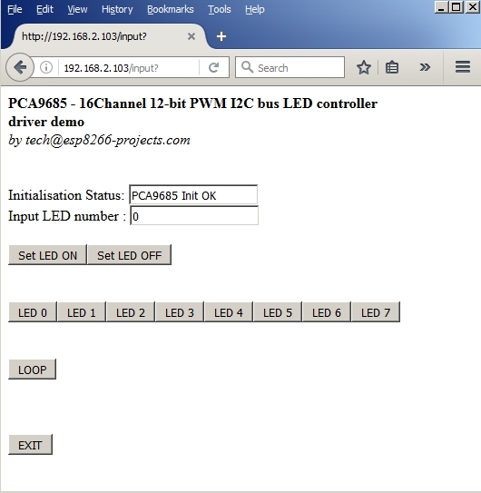
    In the ESP Basic Web editor interface Type & Save your program as "PCA9685.bas" and Run it.  
    If all OK the result should look as below:


    Monday, November 14, 2016

    Mailbag - PCF8591 I2C 8 bit ADC/DAC Driver - Part 2


    ESP Basic series -  I2C driver example for the PCF8591 I2C 8-bit A/D and D/A converter - PART2

    For a deeper description of the PCF8591 and simple DAC driver example please go to PART 1


     What we will need:


        Connection with the ESP8266 nEXT EVO Board is very easy, as PCF8591 Module connector is fully compatible with the nEXT Bus connector.


    Driver implementation
    As been a I2C compatible device you need to have a standard I2C Bus Initialisation function as usual and also to know the I2C address of the device.  
    For a detailed PCF 8591 Control Byte description go to PART1.


    Software: 

    1. Main program: 
     
    let address = 72   'PCF8591 I2C Address
    i2c.setup(4,5)       'choose your I2C bus pins

    cls
    let dac = 0
    let dac_v = 0
    let adc0_1 = 0
    let adc0_v = 0
    let v_cal = 0.0128

    adc0_1 = "ADC stopped"

    wprint " <b>PCF8591 8-bit A/D and D/A converter driver demo</b><br><i>by tech@esp8266-projects.com</i><br><br> "

    wprint " Input DAC value"
    textbox dac

    button " Set Value ",[SetDAC]

    wprint " <br>DAC Output (V)"
    textbox dac_v

    wprint "<br>"

    wprint "<br><br>ADC0 Read Value:"
    textbox adc0_1

    wprint "<br>ADC0 Read (Volt):"
    textbox adc0_v
    wprint "<br><br>"
     
    button " Start ADC_0 ",[ADC0]
    button " Stop ADC", [Exit ADC]

    wprint "<br><br>"
    button " Stop Program", [Exit]

    wait


    2. Set DAC subroutine: 

     [SetDAC]
    dac_v = dac * v_cal

    i2c.begin(address)
    i2c.write(64)  'DAC Enable
    delay 5
    i2c.write(dac)
    i2c.end()
    wait


    3. Enable ADC subroutine:

    [ADC0]
    timer 1000, [readADC]
    wait


    4. Read ADC subroutine:
     
    [readADC]
    ch = 64
    i2c.begin(address)               'start another transaction
    i2c.write(ch)                         'point to the ADC_0 - keep DAC ON
    delay 5
    i2c.end()                                'end write transaction

    i2c.begin(address)                 'start another transaction
    i2c.requestfrom(address,2)    'start a transaction to read 2 bytes
    delay 5
    adc0_0 = i2c.read()              'read the 1st byte
    adc0_1 = i2c.read()              'read the 2nd byte
    i2c.end()                                'end read transaction
    adc0_v = v_cal + adc0_1 * v_cal
    wait


    5. EXIT ADC subroutine:
     
    [Exit ADC]
    timer 0
    adc0_1 = "ADC stopped"
    wait


    6. Exit Program button subroutine:
     
    [Exit]
    timer 0
    end


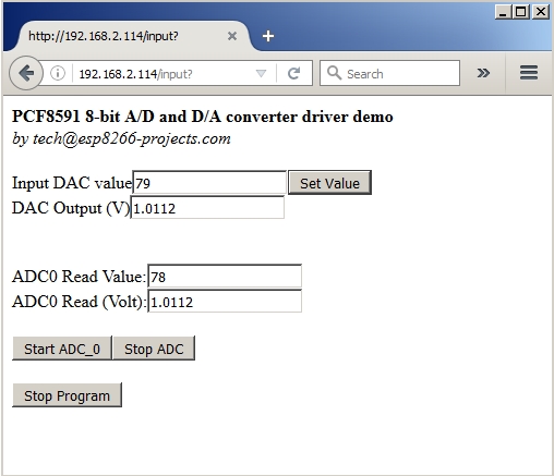
    In the ESP Basic Web editor interface Type & Save your program as "PCF8591.bas" and Run it.  

    If all OK the result should look as below: