ESP8266 Projects Blog
Home of CBDB / MPDMv4 /SmartMon Development boards (ESP-12/ESP-07).
Guidelines and ESP8266 programming examples using LUA, Eclipse and Arduino IDE, ESP Basic and many more!
I was looking a few days ago for a I2C EEPROM to do some tests with ESPBasic and the results...can be seen below :)
1. MAIN Program
cls i2c.setup(4,5) 'choose your I2C bus pins
let eeprom_address = 0 'EEPROM memory start address i2c_address = 87 ' 0x57 - AT24C32 I2C address let i = 0 stw = "87654321" 'string that we want to save in EEPROM
i = 1 do stru = mid(stw,i,1) print "Value to Write: " & asc(stru) i2c.write(asc(stru)) i = i + 1 loop while i < stwl+1 i = 0 i2c.end() print "Write complete" wait
Of course, this is just a proof of concept driver example for the I2C 24C32 EEPROM but I think might help you with a good start :)
PCF8591 Module like the one from here or here, advertised as new versions.
For programming and uploading the driver and the software we will use the ESPBasic
Connection with the ESP8266 nEXT EVO Board is very easy, asPCF8591 Moduleconnector
is fully compatible with the nEXT Bus connector.
Driver implementation As been a I2C compatible device you need to have a standard I2C Bus Initialisation function as usual and also to know the I2C address of the device. For a detailed PCF 8591 Control Byte description go to PART1.
Software:
1. Main program:
let address = 72 'PCF8591 I2C Address i2c.setup(4,5) 'choose your I2C bus pins
cls let dac = 0 let dac_v = 0 let adc0_1 = 0 let adc0_v = 0 let v_cal = 0.0128
ESP Basic series - I2C driver example for the PCF8591 I2C 8-bit A/D and D/A converter. General view:
The PCF8591 is a single-chip, single-supply low-power 8-bit CMOS data acquisition device with four analog inputs, one analog output and a serial I2C-bus interface. Three address pins A0, A1 and A2 are used for programming the hardware address, allowing the use of up to eight devices connected to the I2C-bus without additional hardware. Address, control and data to and from the device are transferred serially via the two-line bidirectional I2C-bus.
The functions of the device include analog input multiplexing, on-chip track and hold function, 8-bit analog-to-digital conversion and an 8-bit digital-to-analog conversion. The maximum conversion rate is given by the maximum speed of the I2C-bus.
Features:
Single power supply
Operating supply voltage 2.5 V to 6.0 V
Low standby current
Serial input and output via I2C-bus
I2C address selection by 3 hardware address pins
Max sampling rate given by I2C-bus speed
4 analog inputs configurable as single ended or differential inputs
PCF8591 Module like the one from here or here, advertised as new versions.
For programming and uploading the driver and the software we will use the ESPBasic
Connection with the ESP8266 nEXT EVO Board is very easy, asPCF8591 Moduleconnector
is fully compatible with the nEXT Bus connector.
Driver implementation
As been a I2C compatible device you need to have a standard I2C Bus Initialisation function as usual and also to know the I2C address of the device.
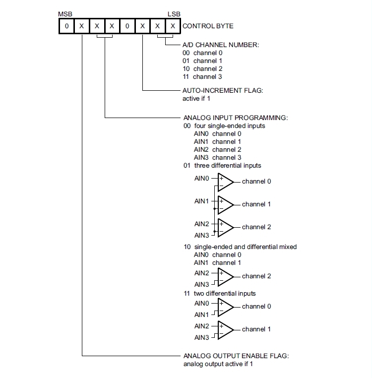
Control Byte is the second byte sent to a PCF8591 device and is stored in its control register and is required to control the device function :
Things to take care about:
The upper nibble of the control register is used for enabling the analog output, and for programming the analog inputs as single-ended or differential inputs. The lower nibble selects one of the analog input channels defined by the upper nibble .
If the auto-increment flag is set, the channel number is incremented automatically after each A/D conversion. If the auto-increment mode is desired in applications where the internal oscillator is used, the analog output enable flag must be set in the control byte (bit 6). This allows the internal oscillator to run continuously, by this means preventing conversion errors resulting from oscillator start-up delay.
The analog output enable flag can be reset at other times to reduce quiescent power consumption.
The selection of a non-existing input channel results in the highest available channel number being allocated. Therefore, if the auto-increment flag is set, the next selected channel is always channel 0.
The most significant bits of both nibbles are reserved for possible future functions and must be set to logic 0. After a Power-On Reset (POR) condition, all bits of the control register are reset to logic 0. The D/A converter and the oscillator are disabled for power saving. The analog output is switched to a high-impedance state.
Software:
1. Main program:
let address = 72 'PCF8591 I2C Address i2c.setup(4,5) 'choose your I2C bus pins cls let dac = 0 let dac_v = 0 let v_cal = 0.0128 wprint " <b>PCF8591 - 8-bit A/D and D/A converter driver <br>DAC demo</b><br><i>by tech@esp8266-projects.com</i><br><br> " wprint " Input DAC value" textbox dac button " Set Value ",[SetDAC] wprint " <br>DAC Output (V)" textbox dac_v wprint "<br><br>" button " Stop Program", [Exit] wait
In the ESP Basic Web editor interface Type & Save your program as "PCF8591.bas" and Run it.
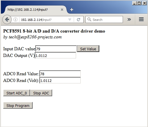
If all OK the result should look as below:
If you want your program to start automatically at reboot/power ON then just Save it as "default.bas" and also from Settings Tab enable the "Run default.bas at startup".
Be aware that at start-up/reboot, it is a delay before your program will start automatically.
In the next part about PCF8591 we will talk about the ADC Driver implementation.
As been requested by many people that have difficulties to use the
MPU6050 Modules, I've done a more detailed ESP8266 Video Tutorial
related with the MPU6050 GY-521 Module initialisation and basic usage.
It is a detailed, step-by-step tutorial, showing all the needed init stages and tests for a proper and smooth usage of the MPU6050 GY-521 module.
These ones seems to work OK connected directly to the 3.3V power on the ESP8266 nEXT EVO board Bus and looks to have some very low dropout voltage regulator. This are the good news about.
Now some bad news: it seems to be sold different types/flavours of modules (maybe old/new batches with various BOM) under the same name code so your experience may vary and might be necessary to use 5V power input for the GY-521. Or just bypass the Voltage Regulator to avoid any wiring around :).
MPU-60X0 Overview
The MPU-60X0 is the world’s first integrated 6-axis MotionTracking device that combines a 3-axis gyroscope, 3-axis accelerometer, and a Digital Motion Processor™ (DMP) all in a small 4x4x0.9mm package.
With its dedicated I2C sensor bus, it directly accepts inputs from an external 3-axis compass to provide a complete 9-axis MotionFusion™ output. It is also designed to interface with multiple non-inertial digital sensors, such as pressure sensors, on its auxiliary I2C port.
So, it can act as a I2C master for other I2C devices. That's cool!
For power supply flexibility, the MPU-60X0 operates from VDD power supply voltage range of 2.375V-3.46V. Additionally, the MPU-6050 provides a VLOGIC reference pin (in addition to its analog supply pin: VDD), which sets the logic levels of its I2C interface. The VLOGIC voltage may be 1.8V±5% or VDD.
The MPU-6000 and MPU-6050 are identical, except that the MPU-6050 supports the I2C serial interface only, and has a separate VLOGIC reference pin. The MPU-6000 supports both I2C and SPI interfaces and has a single supply pin, VDD, which is both the device’s logic reference supply and the analog supply for the part.
MPU-60X0 Features
1. Gyroscope Features
The triple-axis MEMS gyroscope in the MPU-60X0 includes a wide range of features:
Digital-output X-, Y-, and Z-Axis angular rate sensors (gyroscopes) with a user-programmable full-scale range of ±250, ±500, ±1000, and ±2000°/sec
External sync signal connected to the FSYNC pin supports image, video and GPS synchronization
Integrated 16-bit ADCs enable simultaneous sampling of gyros
Enhanced bias and sensitivity temperature stability reduces the need for user calibration
Improved low-frequency noise performance
Digitally-programmable low-pass filter
Gyroscope operating current: 3.6mA
Standby current: 5μA
Factory calibrated sensitivity scale factor
User self-test
2. Accelerometer Features
The triple-axis MEMS accelerometer in MPU-60X0 includes a wide range of features:
Digital-output triple-axis accelerometer with a programmable full scale range of ±2g, ±4g, ±8g and ±16g
Integrated 16-bit ADCs enable simultaneous sampling of accelerometers while requiring no external multiplexer
Accelerometer normal operating current: 500μA
Low power accelerometer mode current: 10μA at 1.25Hz, 20μA at 5Hz, 60μA at 20Hz, 110μA at 40Hz
Orientation detection and signaling
Tap detection
User-programmable interrupts
High-G interrupt
User self-test
3. Additional Features
The MPU-60X0 includes the following additional features:
9-Axis MotionFusion by the on-chip Digital Motion Processor (DMP)
Auxiliary master I2C bus for reading data from external sensors (e.g., magnetometer)
3.9mA operating current when all 6 motion sensing axes and the DMP are enabled
Smallest and thinnest QFN package for portable devices: 4x4x0.9mm
Minimal cross-axis sensitivity between the accelerometer and gyroscope axes
1024 byte FIFO buffer reduces power consumption by allowing host processor to read the data in bursts and then go into a low-power mode as the MPU collects more data
Digital-output temperature sensor
User-programmable digital filters for gyroscope, accelerometer, and temp sensor
10,000 g shock tolerant
400kHz Fast Mode I2C for communicating with all registers
1MHz SPI serial interface for communicating with all registers (MPU-6000 only)
20MHz SPI serial interface for reading sensor and interrupt registers (MPU-6000 only)
MEMS structure hermetically sealed and bonded at wafer level
RoHS and Green compliant
4. MotionProcessing
Internal Digital Motion Processing™ (DMP™) engine supports 3D MotionProcessing and gesture recognition algorithms
The MPU-60X0 collects gyroscope and accelerometer data while synchronizing data sampling at a user defined rate. The total dataset obtained by the MPU-60X0 includes 3-Axis gyroscope data, 3-Axis accelerometer data, and temperature data. The MPU’s calculated output to the system processor can also include heading data from a digital 3-axis third party magnetometer.
The FIFO buffers the complete data set, reducing timing requirements on the system processor by allowing the processor burst read the FIFO data. After burst reading the FIFO data, the system processor can save power by entering a low-power sleep mode while the MPU collects more data.
Programmable interrupt supports features such as gesture recognition, panning, zooming, scrolling, tap detection, and shake detection
Digitally-programmable low-pass filters
Low-power pedometer functionality allows the host processor to sleep while the DMP maintains the step count.
5.5 Clocking
On-chip timing generator ±1% frequency variation over full temperature range
Optional external clock inputs of 32.768kHz or 19.2MHz
It is quite a beast in a tiny package, with Gyroscope, Accelerometer, DMP and all the other goodies inside. For more details please take a look at the MPU60x0 Datasheet
For programming and uploading the driver and the software we will continue to use the LuaUploader as before.
Connection with the ESP8266 nEXT EVO Board is very easy, asMPU6050 GY-521 Moduleconnector
is fully compatible with the nEXT Bus connector. Depending on how to you
choose you socket type, you can install it on TOP or Bottom of the ESP8266 nEXT EVO Board :
MPU6050 GY-521 Module on top of the ESP8266 nEXT Evo Board
Driver implementation
1. Init I2C bus/interface
Standard I2C Bus Initialisation function:
function init_I2C() i2c.setup(bus, sda, scl, i2c.SLOW) end
2. READ MPU6050 Register
Before reading data from MPU6050, you must tell it which of its internal addresses you want to read
A read starts off by writing to the MPU6050
Procedure:
Send a start sequence.
Send I2C address of the device with the R/W bit low (i2c.TRANSMITTER)
Send the Internal register address
Stop sequence
Send a start sequence again (repeated start)
Send the I2C address of the device with the R/W bit high (i2c.RECEIVER)
Read data byte from the register
Send the stop sequence.
function read_reg_MPU(reg) i2c.start(bus) i2c.address(bus, dev_addr, i2c.TRANSMITTER) i2c.write(bus, reg) i2c.stop(bus) i2c.start(bus) i2c.address(bus, dev_addr, i2c.RECEIVER) c=i2c.read(bus, 1) i2c.stop(bus) --print(string.byte(c, 1)) return c end
3. WRITE MPU6050 Register
Procedure:
Send a start sequence
Send the I2C address of the MPU6050 with the R/W bit low (i2c.TRANSMITTER)
Send the internal register number you want to write to
Send the data byte
IF you want more data to be sent can be done here. MPU6050 will automatically increment the internal register address after each byte
Send the stop sequence.
function write_reg_MPU(reg,val) i2c.start(bus) i2c.address(bus, dev_addr, i2c.TRANSMITTER) i2c.write(bus, reg) i2c.write(bus, val) i2c.stop(bus) end
4. INIT MPU6050
When power up, MPU6050 will start in SLEEP mode. To be able to use it you need to START the device.
Procedure:
Set SLEEP bit = 0 in the Power Management Register (107) OR Clear the Register
function init_MPU(reg,val) --(107) 0x6B / 0 write_reg_MPU(reg,val) end
5. MPU6050 connectivity
MPU6050 connectivity status only!
Be sure that you have properly initialised I2C Bus before!
function status_MPU(dev_addr) i2c.start(bus) c=i2c.address(bus, dev_addr ,i2c.TRANSMITTER) i2c.stop(bus) if c==true then print(" Device found at address : "..string.format("0x%X",dev_addr)) else print("Device not found !!") end end
6. Check MPU6050 Status
Using the status_MPU() function and the Who Am I register to check if the MPU6050 is available and alive before doing anything else.
function check_MPU(dev_addr) print("") status_MPU(0x68) read_reg_MPU(117) --Register 117 – Who Am I - 0x75 if string.byte(c, 1)==104 then print(" MPU6050 Device answered OK!") else print(" Check Device - MPU6050 NOT available!") return end read_reg_MPU(107) --Register 107 – Power Management 1-0x6b if string.byte(c, 1)==64 then print(" MPU6050 in SLEEP Mode !") else print(" MPU6050 in ACTIVE Mode !") end end
7. READ MPU6050 RAW DATA
Reading RAW data from the MPU6050. No conversion or transformation si done.
Received Data is in 2 complement format.
Procedure:
Send a start sequence.
Send I2C address of the device with the R/W bit low (i2c.TRANSMITTER)
Send the Internal register address
Stop sequence
Send a start sequence again (repeated start)
Send the I2C address of the device with the R/W bit high (i2c.RECEIVER)
Read the number of the requested data bytes from the registers