ESP8266 Projects Blog
Home of CBDB / MPDMv4 /SmartMon Development boards (ESP-12/ESP-07).
Guidelines and ESP8266 programming examples using LUA, Eclipse and Arduino IDE, ESP Basic and many more!
PCF8591 Module like the one from here or here, advertised as new versions.
For programming and uploading the driver and the software we will use the ESPBasic
Connection with the ESP8266 nEXT EVO Board is very easy, asPCF8591 Moduleconnector
is fully compatible with the nEXT Bus connector.
Driver implementation As been a I2C compatible device you need to have a standard I2C Bus Initialisation function as usual and also to know the I2C address of the device. For a detailed PCF 8591 Control Byte description go to PART1.
Software:
1. Main program:
let address = 72 'PCF8591 I2C Address i2c.setup(4,5) 'choose your I2C bus pins
cls let dac = 0 let dac_v = 0 let adc0_1 = 0 let adc0_v = 0 let v_cal = 0.0128
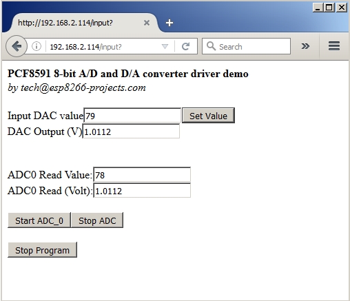
ESP Basic series - I2C driver example for the PCF8591 I2C 8-bit A/D and D/A converter. General view:
The PCF8591 is a single-chip, single-supply low-power 8-bit CMOS data acquisition device with four analog inputs, one analog output and a serial I2C-bus interface. Three address pins A0, A1 and A2 are used for programming the hardware address, allowing the use of up to eight devices connected to the I2C-bus without additional hardware. Address, control and data to and from the device are transferred serially via the two-line bidirectional I2C-bus.
The functions of the device include analog input multiplexing, on-chip track and hold function, 8-bit analog-to-digital conversion and an 8-bit digital-to-analog conversion. The maximum conversion rate is given by the maximum speed of the I2C-bus.
Features:
Single power supply
Operating supply voltage 2.5 V to 6.0 V
Low standby current
Serial input and output via I2C-bus
I2C address selection by 3 hardware address pins
Max sampling rate given by I2C-bus speed
4 analog inputs configurable as single ended or differential inputs
PCF8591 Module like the one from here or here, advertised as new versions.
For programming and uploading the driver and the software we will use the ESPBasic
Connection with the ESP8266 nEXT EVO Board is very easy, asPCF8591 Moduleconnector
is fully compatible with the nEXT Bus connector.
Driver implementation
As been a I2C compatible device you need to have a standard I2C Bus Initialisation function as usual and also to know the I2C address of the device.
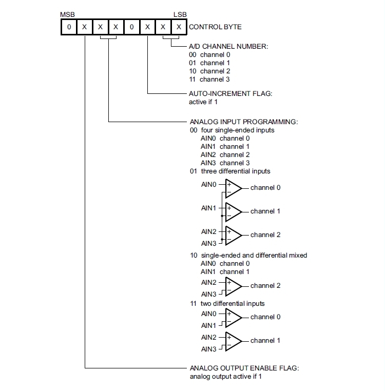
Control Byte is the second byte sent to a PCF8591 device and is stored in its control register and is required to control the device function :
Things to take care about:
The upper nibble of the control register is used for enabling the analog output, and for programming the analog inputs as single-ended or differential inputs. The lower nibble selects one of the analog input channels defined by the upper nibble .
If the auto-increment flag is set, the channel number is incremented automatically after each A/D conversion. If the auto-increment mode is desired in applications where the internal oscillator is used, the analog output enable flag must be set in the control byte (bit 6). This allows the internal oscillator to run continuously, by this means preventing conversion errors resulting from oscillator start-up delay.
The analog output enable flag can be reset at other times to reduce quiescent power consumption.
The selection of a non-existing input channel results in the highest available channel number being allocated. Therefore, if the auto-increment flag is set, the next selected channel is always channel 0.
The most significant bits of both nibbles are reserved for possible future functions and must be set to logic 0. After a Power-On Reset (POR) condition, all bits of the control register are reset to logic 0. The D/A converter and the oscillator are disabled for power saving. The analog output is switched to a high-impedance state.
Software:
1. Main program:
let address = 72 'PCF8591 I2C Address i2c.setup(4,5) 'choose your I2C bus pins cls let dac = 0 let dac_v = 0 let v_cal = 0.0128 wprint " <b>PCF8591 - 8-bit A/D and D/A converter driver <br>DAC demo</b><br><i>by tech@esp8266-projects.com</i><br><br> " wprint " Input DAC value" textbox dac button " Set Value ",[SetDAC] wprint " <br>DAC Output (V)" textbox dac_v wprint "<br><br>" button " Stop Program", [Exit] wait
In the ESP Basic Web editor interface Type & Save your program as "PCF8591.bas" and Run it.
If all OK the result should look as below:
If you want your program to start automatically at reboot/power ON then just Save it as "default.bas" and also from Settings Tab enable the "Run default.bas at startup".
Be aware that at start-up/reboot, it is a delay before your program will start automatically.
In the next part about PCF8591 we will talk about the ADC Driver implementation.
WARNING!! You will play with LIVE MAINS!! Deadly zone!!
If you don't
have any experience and are not qualified for working with MAINS power I
will not encourage you to play arround!. The
author take no responsibility for any injury or
death resulting, directly or indirectly, from your inability to
appreciate the hazards of household mains voltages.
The circuit diagrams are as accurately as possible, but are offered with no
guarantees whatsoever.
There is no guarantee that this design meets any Rules which may be in
force in your country so please check before your local
rules/regulations.
For any new orders/requests please feel free to use as usual: tech at esp8266-projects.com. MPDMv4 Boards are also available on Tindie: AC MAINS Dimmer - MPDMv4
As been a Voltage controled AC MAINS Dimmer you can control it with:
PWM signal
DAC output Voltage
or if you don't want any kind of MCU involved, just user a 10k Potentiometer in a voltage divider as part of a simple VCNT input circuit!
In this example we will use a MCP4728 4 channels/12 Bit DAC as a VCNT (voltage control) command source for our MPDMv4 Dimmer Board.
Now, with a nice and powerful 12 bit DAC working on our ESP8266 CBDB Board ( see Part 1 ) let's test it to the limit a little bit. As you will see from the Oscilloscope and DMM images below, MCP4726 DAC Output it's nice, smooth and stable. Not bad at all for a 1$ range DAC!
First step: DAC Output voltage programmed at 0.5V
Oscilloscope - 0.5V DAC Output
DMM - 0.5V DAC Output
What do you think about generating some standard waveforms with ESP8266 CBDB Board ? :) 1. Square Wave
function squareWave(nrit) local t=0 while t<nrit do mcp4726:write_dac(2.5) tmr.delay(500000) tmr.wdclr() mcp4726:write_dac(0) tmr.delay(500000) tmr.wdclr() t=t+1 end end
Oscilloscope - Square Wave DAC Output
DMM -Square Wave DAC Output
2. Sawtooth Wave
function sawtoothWave(nrit) local t=0 while t<nrit do for i=0,3,0.01 do mcp4726:write_dac(i) --tmr.delay(100) tmr.wdclr() end t=t+1 end mcp4726:write_dac(0) end
Oscilloscope - Sawtooth Wave DAC Output
DMM - Sawtooth Wave DAC Output
3. Triagle Wave
function triangleWave(nrit) local t=0 while t<nrit do for i=0,3,0.01 do mcp4726:write_dac(i) --tmr.delay(100) tmr.wdclr() end for i=3,0,-0.01 do mcp4726:write_dac(i) --tmr.delay(100) tmr.wdclr() end t=t+1 end end
Oscilloscope - Triangle Wave DAC Output
DMM - Triangle Wave DAC Output
4. SIN Wave
For this one we will use a predefined table with calculated SIN points values:
function sinWave(nrit) local sn=0 while sn<nrit do for f = 1, #s1 do v = string.format("%f",s1[f]) --print(v) mcp4726:write_dac(v) --tmr.delay(1) tmr.wdclr() end sn=sn+1 end end
Oscilloscope - SIN Wave DAC Output
DMM - SIN Wave DAC Output
For programming and uploading the software we will continue to use the LuaUploader as before.
To run the test, just save the code on ESP as 'func_gen.lua', restart ESP and run:
If you run in problems regarding available memory (should not if running after proper ESP Module restart) or want to optimise the memory usage just compile the program and driver before execution: node.compile('mcp4726.lua') node.compile('func_gen.lua')
At least from the zillions of request for a DAC Driver implementation example that I received in the latest weeks, this is the long awaited topic: ESP8266 Modules and Voltage Output Digital-to-Analog Converter control!
For our project we will use Microchip MCP4726, a Voltage Output Digital-to-Analog Converter (DAC) with EEPROM and I2C™ Interface.
As you will see, despite the fact that is a tiny one, it's a very versatile chip with a great price/capabilities ratio. If you take a look on Digikey for example it can be found at around 1.15$! Features:
The VREF pin or the device VDD can be selected as the DAC’s reference voltage. When VDD is selected, VDD is connected internally to the DAC reference circuit. When the VREF pin is used, the user can select the output buffer’s gain to 1 or 2. When the gain is 2, the VREF pin voltage should be limited to a maximum of VDD/2.
That means that it has also an internal reference and if you don't need very high accuracy or you have a very stable power supply for MCP4726 DAC, you don't need to use an external expensive Voltage Reference to make it working decent! If you are looking in the basement after boson Higgs cousin then this 1.15$ DAC is not what are you looking for :)
• Output Gain Options:
- Unity (1x)
- 2x, only when VREF pin is used as voltage
source
• Nonvolatile Memory (EEPROM):
- Auto Recall of Saved DAC register setting
- Auto Recall of Saved Device Configuration
(Voltage Reference, Gain, Power-Down)
• Power-Down modes:
- Disconnects output buffer
- Selection of VOUT pull-down resistors
(640 kΩ, 125 kΩ, or 1 kΩ) • Low-Power Consumption:
- Normal Operation: 210 μA typical
- Power-Down Operation: 60 nA typical
(PD1:PD0 = 11)
• Single-Supply Operation: 2.7V to 5.5V
• I2C™ Interface:
- Eight Available Addresses - Factory hardcoded !! - if you need more than one to run in your project be carefully when ordering!!
- Standard (100 kbps), Fast (400 kbps), and
High-Speed (3.4 Mbps) modes
• Small 6-lead SOT-23 and DFN (2x2) Packages • Extended Temperature Range: -40°C to +125°C
Don't
be scared by the SOT-23 package used, with a small SOT-23 to DIP adapter will
fit great in our CBDB extension slots so it will not matter at all. Actually is even more manageable than the MCP9808 Temperature sensor MSOP-8 package used before
USB adapter (take a look on Part 1 for details how to connect them together)
MCP4726 Module from above
LED module (if you want maybe a LED ticker)
CBDB with MCP4726 DAC and MCP9808 Temperature Modules
Connection between the modules is pretty simple as both are I2C chip modules. Each of them is connected at +3V, GND and toghether on I2C bus using SDA and SCL lines. I will suggest also to do proper decoupling for MCP4726 Power and Vout pins (see picture above).
MCP4726 DAC Module connections
Please remember that all released software examples are provided under MIT Licence, if no other specific options stated. I was asked about, so this is the reason of this declaration. Some people looks more interested in legal stuff than wide access to information. So, if you find on this website anything useful and you want to contribute, please send your comments or even a donation. OR virtual beer. OR whaterver. OR nothing. Your choice. ---------------------------------------------------------------------------------------------------------------------------- The MIT License (MIT)
Copyright (c) 2015 esp8266-projects.com
Permission is hereby granted, free of charge, to any person obtaining a copy of this software and associated documentation files (the "Software"), to deal in the Software without restriction, including without limitation the rights to use, copy, modify, merge, publish, distribute, sublicense, and/or sell copies of the Software, and to permit persons to whom the Software is furnished to do so, subject to the following conditions: The above copyright notice and this permission notice shall be included in all copies or substantial portions of the Software.
THE SOFTWARE IS PROVIDED "AS IS", WITHOUT WARRANTY OF ANY KIND, EXPRESS OR IMPLIED, INCLUDING BUT NOT LIMITED TO THE WARRANTIES OF MERCHANTABILITY, FITNESS FOR A PARTICULAR PURPOSE AND NONINFRINGEMENT. IN NO EVENT SHALL THE AUTHORS OR COPYRIGHT HOLDERS BE LIABLE FOR ANY CLAIM, DAMAGES OR OTHER LIABILITY, WHETHER IN AN ACTION OF CONTRACT, TORT OR OTHERWISE, ARISING FROM, OUT OF OR IN CONNECTION WITH THE SOFTWARE OR THE USE OR OTHER DEALINGS IN THE SOFTWARE. ----------------------------------------------------------------------------------------------------------------------------
For programming and uploading the driver and the software we will continue to use the LuaUploader as before.
Driver implementation. As MCP4726 has a I2C compatible compatible interface, building a driver for it it's a pretty straigh forward process: 1. Init I2C bus/interface dev_addr = 0x60, init = function (self, sda, scl) self.id = 0 i2c.setup(self.id, sda, scl, i2c.SLOW) end