Showing posts with label ESPBasic. Show all posts

Monday, April 24, 2017

ESPBasic - Web Interface - CSS elements example

A quick example on how to change your Web interface GUI objects properties without using a separate CSS file.

Reading Himidity and Temperature from a DHT22 Sesor connected to the GPIO5 and also retrieving Date and Time from NTP Server:

PinDHT = 5
DHT.SETUP(22, PinDHT)

cls

timer 1000, [branch] ' ## Time for auto refresh variables ##

wprint |<body style="background-color:powderblue;">|
wprint |<H1><span style="color: red;">|
wprint "Example for changing GUI object properties with CSS"
wprint "</H1>"
wprint "</span>"

wprint "<table border='1'><tr><td>Date</td><td>"
textbox Dtm
cssid htmlid(), "background-color: yellow;display:block;width:160px"
wprint "</td></tr><tr><td>Humidity </td><td>"
textbox Hum
cssid htmlid(), "background-color: grey;color:#F00;display:block;width:40px"
wprint "</td></tr><tr><td>Temperature Deg C</td><td>"
textbox Temp
cssid htmlid(), "background-color: #ccaabb;display:block;width:40px"

wprint "</td></tr></table><p>"

wprint "<p> Click to Exit <br>"
button "Exit", [TestExit]

Wait


[TestExit]
timer 0
end

[branch]
gosub [readdata]
wait

[readdata]
Dtm = time() 'Current Date and Time
Temp = DHT.TEMP() 'Current Temperature
Hum = DHT.HUM() 'Current Humidity


The result looks as below:


Friday, April 21, 2017

ESPBasic Series: Web Interface Slider demo


How easy or complicated is in ESPBasic to have a instant response slider for your MPDMv4 AC Dimmer Web interface?

Just look at the code below:
cls
let xpv = 0
let PWMpin = 5
slider x,150,900
timer 500, [set.dimmer]
wprint "<br><br>"
button " Exit ", [TestExit]

wait

[set.dimmer]
 if x <> xpv then
   io(pwo,PWMpin,x)
   xpv = x
 end if
wait

[TestExit]
wprint |<a href="./edit"> Edit</a>|
end

 Yes, it's all there, plus some extras :)

The Power of ESPBasic !

Friday, February 24, 2017

ESPBasic Series : Decimal-to-Binary conversion


   I was looking a while ago to implement some Decimal-to-Binary conversion subroutine to be used for easy visualisation of the Registry content. Been able to see the values directly binary can help a lot when developping a driver for a IC or any piece of related software:


1. Decimal-to-Binary subroutine:
 [decbin]
  i = 1
  r = 0
  binval = 0
  nr = decval
 Do
   r = nr % 2
   nr = int(nr/2)
   binval = binval + r*i
   i = i*10
 Loop while nr > 0
wait

  2. Test Program:
decval = 0
binval = 0
wprint "<br><br>Decimal value "

textbox decval
button " Convert ", [decbin]

wprint "<br><br> Binary value "
textbox binval
wprint "<br><br>"
button " Exit ", [TestExit] 
Wait

[TestExit]
 Looking forward to see your own ideas about!

Happy breadboarding,
TJ.

Thursday, February 16, 2017

ESPBasic Series - DEC to BCD and BCD to DEC conversions


In the process of working on a new Driver Tutorial for the ESPBasic Series I am looking today to implement some Decimal-to-BCD and BCD-to-Decimal subroutines.

What I have done so far:

1. BCD-to-Decimal subroutine:
[DEC]
hv = val >> 4
hl = val and 15
val = hv*10 + hl
wait 
 2. Decimal-to-BCD subroutine:
[BCD]
d = int( val / 10 )
d1 = d * 10
d2 = val - d1
val = d*16 + d2
wait

 3. Test Program
let val = 96
textbox val
button "To DEC", [DEC]
button "To BCD", [BCD]
wprint "<br><br>"
button " Exit ", [TestExit]
wait

[TestExit]
end


If you have any other idea please feel free to share it, looking forward to see smarter solutions that that. I'm sure they are!

Happy breadboarding,
TJ.

Monday, January 9, 2017

ESPBasic driver example for AT24C32 - I2C EEPROM


Do you remember the widely used DS3231 RTC Module

As you might rememeber we have identified onboard an EEPROM chip, a 32k AT24C32 one and have written some driver examples for LUA 

I was looking a few days ago for a I2C EEPROM to do some tests with ESPBasic and the results...can be seen below :)

1. MAIN Program
cls
i2c.setup(4,5)                    'choose your I2C bus pins

let eeprom_address = 0    'EEPROM memory start address
i2c_address = 87              ' 0x57 - AT24C32 I2C address
let i = 0
stw = "87654321"            'string that we want to save in EEPROM

button "i2c Read",[I2C_read]
button "i2c Write",[I2C_Write]
wait

2. EEPROM READ Function


[I2C_read]
  stwl = len(stw)
  print "Reading from I2C address " & i2c_address
  adrh = eeprom_address >> 8
  adrl = eeprom_address and 255

  i2c.begin(i2c_address)
  i2c.write(adrh)
  i2c.write(adrl)
  i2c.end()

  i2c.begin(i2c_address)
  i2c.requestfrom(i2c_address,stwl)
  tr = i2c.available()
  print "Available bytes :" & tr
  do
      i2c_read = i2c.read()
      readt = i2c_read-48
      print  "Read value : " & readt
      i = i + 1
  loop while i < tr
  i = 0
  i2c.end()
  print "Read complete"
wait


3. EEPPROM WRITE function

[I2C_Write]
 print "Writing to I2C address " & i2c_address

 stwl = len(stw)
 print "String : " & stw
 print "String Lenght : " & stwl

 adrh = eeprom_address >> 8
 adrl = eeprom_address and 255

 i2c.begin(i2c_address)
 i2c.write(adrh)
 i2c.write(adrl)

 i = 1
 do
     stru = mid(stw,i,1)
     print  "Value to Write: " & asc(stru)
     i2c.write(asc(stru))
     i = i + 1
 loop while i < stwl+1
 i = 0
 i2c.end()
 print "Write complete"
wait

Of course, this is just a proof of concept driver example for the I2C 24C32 EEPROM but I think might help you with a good start :)


Happy breadboarding,
TJ.

Monday, November 14, 2016

Mailbag - PCF8591 I2C 8 bit ADC/DAC Driver - Part 2


ESP Basic seriesI2C driver example for the PCF8591 I2C 8-bit A/D and D/A converter - PART2

For a deeper description of the PCF8591 and simple DAC driver example please go to PART 1


 What we will need:


    Connection with the ESP8266 nEXT EVO Board is very easy, as PCF8591 Module connector is fully compatible with the nEXT Bus connector.


Driver implementation
As been a I2C compatible device you need to have a standard I2C Bus Initialisation function as usual and also to know the I2C address of the device.  
For a detailed PCF 8591 Control Byte description go to PART1.


Software: 

1. Main program: 
 
let address = 72   'PCF8591 I2C Address
i2c.setup(4,5)       'choose your I2C bus pins

cls
let dac = 0
let dac_v = 0
let adc0_1 = 0
let adc0_v = 0
let v_cal = 0.0128

adc0_1 = "ADC stopped"

wprint " <b>PCF8591 8-bit A/D and D/A converter driver demo</b><br><i>by tech@esp8266-projects.com</i><br><br> "

wprint " Input DAC value"
textbox dac

button " Set Value ",[SetDAC]

wprint " <br>DAC Output (V)"
textbox dac_v

wprint "<br>"

wprint "<br><br>ADC0 Read Value:"
textbox adc0_1

wprint "<br>ADC0 Read (Volt):"
textbox adc0_v
wprint "<br><br>"
 
button " Start ADC_0 ",[ADC0]
button " Stop ADC", [Exit ADC]

wprint "<br><br>"
button " Stop Program", [Exit]

wait


2. Set DAC subroutine: 

 [SetDAC]
dac_v = dac * v_cal

i2c.begin(address)
i2c.write(64)  'DAC Enable
delay 5
i2c.write(dac)
i2c.end()
wait


3. Enable ADC subroutine:

[ADC0]
timer 1000, [readADC]
wait


4. Read ADC subroutine:
 
[readADC]
ch = 64
i2c.begin(address)               'start another transaction
i2c.write(ch)                         'point to the ADC_0 - keep DAC ON
delay 5
i2c.end()                                'end write transaction

i2c.begin(address)                 'start another transaction
i2c.requestfrom(address,2)    'start a transaction to read 2 bytes
delay 5
adc0_0 = i2c.read()              'read the 1st byte
adc0_1 = i2c.read()              'read the 2nd byte
i2c.end()                                'end read transaction
adc0_v = v_cal + adc0_1 * v_cal
wait


5. EXIT ADC subroutine:
 
[Exit ADC]
timer 0
adc0_1 = "ADC stopped"
wait


6. Exit Program button subroutine:
 
[Exit]
timer 0
end


In the ESP Basic Web editor interface Type & Save your program as "PCF8591.bas" and Run it.  

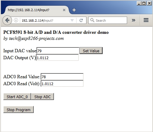
If all OK the result should look as below:


Friday, November 11, 2016

Mailbag - PCF8591 I2C 8 bit ADC/DAC Driver - Part 1


ESP Basic series -  I2C driver example for the PCF8591 I2C 8-bit A/D and D/A converter.


General view:


   The PCF8591 is a single-chip, single-supply low-power 8-bit CMOS data acquisition
device with four analog inputs, one analog output and a serial I2C-bus interface. Three
address pins A0, A1 and A2 are used for programming the hardware address, allowing
the use of up to eight devices connected to the I2C-bus without additional hardware.
Address, control and data to and from the device are transferred serially via the two-line
bidirectional I2C-bus.
 

  The functions of the device include analog input multiplexing, on-chip track and hold
function, 8-bit analog-to-digital conversion and an 8-bit digital-to-analog conversion. The
maximum conversion rate is given by the maximum speed of the I2C-bus.


Features:

  • Single power supply
  • Operating supply voltage 2.5 V to 6.0 V
  • Low standby current
  • Serial input and output via I2C-bus
  • I2C address selection by 3 hardware address pins
  • Max sampling rate given by I2C-bus speed
  • 4 analog inputs configurable as single ended or differential inputs
  • Auto-incremented channel selection
  • Analog voltage range from VSS to VDD
  • On-chip track and hold circuit
  • 8-bit successive approximation A/D conversion
  • Multiplying DAC with one analog output.

For more details please take a look at the PCF8591 Datasheet


What we will need:

    Connection with the ESP8266 nEXT EVO Board is very easy, as PCF8591 Module connector is fully compatible with the nEXT Bus connector.


Driver implementation

As been a I2C compatible device you need to have a standard I2C Bus Initialisation function as usual and also to know the I2C address of the device.

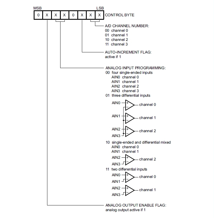
Control Byte is the second byte sent to a PCF8591 device and is stored in its control register and is required to control the device function :


 Things to take care about: 

 The upper nibble of the control register is used for enabling the analog output, and for programming the analog inputs as single-ended or differential inputs. 
  The lower nibble selects one of the analog input channels defined by the upper nibble .

  If the auto-increment flag is set, the channel number is incremented automatically after each A/D conversion. If the auto-increment mode is desired in applications where the internal oscillator is used,
the analog output enable flag must be set in the control byte (bit 6). This allows the
internal oscillator to run continuously, by this means preventing conversion errors
resulting from oscillator start-up delay. 


  The analog output enable flag can be reset at other times to reduce quiescent power consumption.
 

   The selection of a non-existing input channel results in the highest available channel number being allocated. Therefore, if the auto-increment flag is set, the next selected channel is always channel 0. 

   The most significant bits of both nibbles are reserved for possible future functions and must be set to logic 0. After a Power-On Reset (POR) condition, all bits of the control register are reset to logic 0. 
   The D/A converter and the oscillator are disabled for power saving. 
   
  The analog output is switched to a high-impedance state.
 

Software: 

1. Main program: 
 
let address = 72 'PCF8591 I2C Address
i2c.setup(4,5) 'choose your I2C bus pins

cls
let dac = 0
let dac_v = 0
let v_cal = 0.0128

wprint " <b>PCF8591 - 8-bit A/D and D/A converter driver <br>DAC demo</b><br><i>by tech@esp8266-projects.com</i><br><br> "

wprint " Input DAC value"
textbox dac

button " Set Value ",[SetDAC]

wprint " <br>DAC Output (V)"
textbox dac_v

wprint "<br><br>"
button " Stop Program", [Exit]

wait


2. Set DAC subroutine: 

 
[SetDAC]
dac_v = dac * v_cal
i2c.begin(address)
i2c.write(64) 'Enable DAC
delay 5
i2c.write(dac)
i2c.end()
wait


3. EXIT program button:

[Exit]
timer 0
end


In the ESP Basic Web editor interface Type & Save your program as "PCF8591.bas" and Run it.  

 
If all OK the result should look as below:


If you want your program to start automatically at reboot/power ON then just Save it as "default.bas" and also from Settings Tab enable the "Run default.bas at startup".


Be aware that at start-up/reboot, it is a delay before your program will start automatically.


In  the next part about PCF8591 we will talk about the ADC Driver implementation.


Saturday, November 5, 2016

WIFI Dev Board for Home Automation - Part 2


This is Part 2 of the Wifi Dev Board for Home Automation series. For general presentation and hardware description please take a look also at Part 1 of the series


MPRSx8 Board is available also on Tindie store: https://www.tindie.com/stores/nEXT_EVO1/


What we will need:


Software implementation:

As this time we will talk about the Software side we will design a very simple driver for our board that will include also a interactive Web command interface for the MPRSx8 Home Automation Dev Board Relays.

To keep things simple, we will just add in our Web Interface 8 ON/OFF Buttons and one general OFF one, from where we can turn ON/OFF all the Relays switches. 


1. Main Program
cls                       ' clear interface
let address = 56  'PCF8574 I2C Address

i2c.setup(4,5)      'choose your I2C bus pins

i2c.begin(address)
ss = 0 xor 255      'XOR - Bit masking for the desired I/O pins
i2c.write(ss)
i2c.end()
button "x1", [5]    ' Button for Relay 1
button "x2", [6]
button "x3", [7]
button "x4", [8]
button "x5", [1]
button "x6", [2]
button "x7", [3]
button "x8", [4]    ' Button for Relay 8
button "OFF", [9] ' General OFF for all the Relays
wait


2. General OFF for all the Relays subroutine
[9]
i2c.begin(address)
ss = 0 xor 255 'XOR - Bit masking for the desired I/O pins
i2c.write(ss)
i2c.end()
wait


3. Subroutines for each Button
[1]
i2c.begin(address)
ss = ss xor 1   'XOR - Bit masking for the desired I/O pins
i2c.write(ss)
i2c.end()
wait

[2]
i2c.begin(address)
ss = ss xor 2
i2c.write(ss)
i2c.end()
wait

[3]
i2c.begin(address)
ss = ss xor 4
i2c.write(ss)
i2c.end()
wait

[4]
i2c.begin(address)
ss = ss xor 8
i2c.write(ss)
i2c.end()
wait

[5]
i2c.begin(address)
ss = ss xor 16
i2c.write(ss)
i2c.end()
wait

[6]
i2c.begin(address)
ss = ss xor 32
i2c.write(ss)
i2c.end()
wait

[7]
i2c.begin(address)
ss = ss xor 64
i2c.write(ss)
i2c.end()
wait

[8]
i2c.begin(address)
ss = ss xor 128
i2c.write(ss)
i2c.end()
wait


In the Web editor interface Save your program as "test_MPRSx8_1.bas" and Run it.


If all OK the result should look as below:


If you want your program to start automatically at reboot/power ON then just Save it as "default.bas" and also from Settings Tab enable the "Run default.bas at startup".


Be aware that at start-up/reboot, it is a delay before your program will start automatically.


WIFI MAINS 8x Relay Board for Home Automation and more


Available also on Tindie store: https://www.tindie.com/stores/nEXT_EVO1/


Features:
  • Compact, standard size: 16x5 cm! (half Eurocard height)
  • Universal AC MAINS input (240VAC/50Hz (EU) or 110V/60Hz (US)
  • Proper MOV and high quality ceramic FUSE MAINS input protection.
  • 8 x MAINS rated 15A Relays
  • 8 x independent swithing Power Channels 
  • Power Channels can be software configured for mutually exclusive usage
  • Recommended load upto 10A each channel
  • LED signaling Panel for each Power Channel Status 
  • Integrated switchmode MAINS PSU
  • Separate high efficient switchmode PSU for command & control circuit
  • Can work also from a external +12V power supply just not install the MAINS PSU
  • Safe operation design
  • I2C / nEXT Bus compatible - you can add your own extension modules - light sensors, gas, motion, etc
  • Can be stacked upto 8 boards ( 1 Master and 7 slaves) for a total of 64 Power Channels!!
  • Compatible with any I2C compatible MCU: Arduino, ARM, PIC, ATMEGA, ESP8266, ESP32, etc
  • ESP8266 friendly design: can add your ESP8266 module directly onboard for a full WIFI MAINS Power switchboard solution
  • Full access to ESP8266 pins thru 2 headers gives you even more flexibility in developing your projects!
  • Full programming header  (Tx, Rx, GPIO0 and Reset)

Command and control side - pinout details


 Schematics:


MAINS input power supply


3.3V power supply for the command and control section


Relays driver


In Part 2 we will continue with the software side, how to connect, program and use the MPRSx8 Relay board.


Creative Commons License All schematics, boards, software and articles released by ESP8266-Projects.com are licensed under a Creative Commons Attribution-NonCommercial 4.0 International License


Thursday, October 27, 2016

ESP Basic Tutorial - Beep Button


ESP Basic tutorial: How to "beep" your Button in the Web interface using a bit of Javascript :)

Take the code from below and save it in "beep.js" file on your PC

<code>
function beep() {
  (new
    Audio(
    "data:audio/wav;base64,//uQRAAAAWMSLwUIYAAsYkXgoQwAEaYLWfkWgAI0wWs/ItAAAGDgYtAgAyN+QWaAAihwMWm4G8QQRDiMcCBcH3Cc+CDv/7xA4Tvh9Rz/y8QADBwMWgQAZG/ILNAARQ4GLTcDeIIIhxGOBAuD7hOfBB3/94gcJ3w+o5/5eIAIAAAVwWgQAVQ2ORaIQwEMAJiDg95G4nQL7mQVWI6GwRcfsZAcsKkJvxgxEjzFUgfHoSQ9Qq7KNwqHwuB13MA4a1q/DmBrHgPcmjiGoh//EwC5nGPEmS4RcfkVKOhJf+WOgoxJclFz3kgn//dBA+ya1GhurNn8zb//9NNutNuhz31f////9vt///z+IdAEAAAK4LQIAKobHItEIYCGAExBwe8jcToF9zIKrEdDYIuP2MgOWFSE34wYiR5iqQPj0JIeoVdlG4VD4XA67mAcNa1fhzA1jwHuTRxDUQ//iYBczjHiTJcIuPyKlHQkv/LHQUYkuSi57yQT//uggfZNajQ3Vmz+ Zt//+mm3Wm3Q576v////+32///5/EOgAAADVghQAAAAA//uQZAUAB1WI0PZugAAAAAoQwAAAEk3nRd2qAAAAACiDgAAAAAAABCqEEQRLCgwpBGMlJkIz8jKhGvj4k6jzRnqasNKIeoh5gI7BJaC1A1AoNBjJgbyApVS4IDlZgDU5WUAxEKDNmmALHzZp0Fkz1FMTmGFl1FMEyodIavcCAUHDWrKAIA4aa2oCgILEBupZgHvAhEBcZ6joQBxS76AgccrFlczBvKLC0QI2cBoCFvfTDAo7eoOQInqDPBtvrDEZBNYN5xwNwxQRfw8ZQ5wQVLvO8OYU+mHvFLlDh05Mdg7BT6YrRPpCBznMB2r//xKJjyyOh+cImr2/4doscwD6neZjuZR4AgAABYAAAABy1xcdQtxYBYYZdifkUDgzzXaXn98Z0oi9ILU5mBjFANmRwlVJ3/6jYDAmxaiDG3/6xjQQCCKkRb/6kg/wW+kSJ5//rLobkLSiKmqP/0ikJuDaSaSf/6JiLYLEYnW/+kXg1WRVJL/9EmQ1YZIsv/6Qzwy5qk7/+tEU0nkls3/zIUMPKNX/6yZLf+kFgAfgGyLFAUwY//uQZAUABcd5UiNPVXAAAApAAAAAE0VZQKw9ISAAACgAAAAAVQIygIElVrFkBS+Jhi+EAuu+lKAkYUEIsmEAEoMeDmCETMvfSHTGkF5RWH7kz/ESHWPAq/kcCRhqBtMdokPdM7vil7RG98A2sc7zO6ZvTdM7pmOUAZTnJW+NXxqmd41dqJ6mLTXxrPpnV8avaIf5SvL7pndPvPpndJR9Kuu8fePvuiuhorgWjp7Mf/PRjxcFCPDkW31srioCExivv9lcwKEaHsf/7ow2Fl1T/9RkXgEhYElAoCLFtMArxwivDJJ+bR1HTKJdlEoTELCIqgEwVGSQ+hIm0NbK8WXcTEI0UPoa2NbG4y2K00JEWbZavJXkYaqo9CRHS55FcZTjKEk3NKoCYUnSQ 0rWxrZbFKbKIhOKPZe1cJKzZSaQrIyULHDZmV5K4xySsDRKWOruanGtjLJXFEmwaIbDLX0hIPBUQPVFVkQkDoUNfSoDgQGKPekoxeGzA4DUvnn4bxzcZrtJyipKfPNy5w+9lnXwgqsiyHNeSVpemw4bWb9psYeq//uQZBoABQt4yMVxYAIAAAkQoAAAHvYpL5m6AAgAACXDAAAAD59jblTirQe9upFsmZbpMudy7Lz1X1DYsxOOSWpfPqNX2WqktK0DMvuGwlbNj44TleLPQ+Gsfb+GOWOKJoIrWb3cIMeeON6lz2umTqMXV8Mj30yWPpjoSa9ujK8SyeJP5y5mOW1D6hvLepeveEAEDo0mgCRClOEgANv3B9a6fikgUSu/DmAMATrGx7nng5p5iimPNZsfQLYB2sDLIkzRKZOHGAaUyDcpFBSLG9MCQALgAIgQs2YunOszLSAyQYPVC2YdGGeHD2dTdJk1pAHGAWDjnkcLKFymS3RQZTInzySoBwMG0QueC3gMsCEYxUqlrcxK6k1LQQcsmyYeQPdC2YfuGPASCBkcVMQQqpVJshui1tkXQJQV0OXGAZMXSOEEBRirXbVRQW7ugq7IM7rPWSZyDlM3IuNEkxzCOJ0ny2ThNkyRai1b6ev//3dzNGzNb//4uAvHT5sURcZCFcuKLhOFs8mLAAEAt4UWAAIABAAAAAB4qbHo0tIjVkUU//uQZAwABfSFz3ZqQAAAAAngwAAAE1HjMp2qAAAAACZDgAAAD5UkTE1UgZEUExqYynN1qZvqIOREEFmBcJQkwdxiFtw0qEOkGYfRDifBui9MQg4QAHAqWtAWHoCxu1Yf4VfWLPIM2mHDFsbQEVGwyqQoQcwnfHeIkNt9YnkiaS1oizycqJrx4KOQjahZxWbcZgztj2c49nKmkId44S71j0c8eV9yDK6uPRzx5X18eDvjvQ6yKo9ZSS6l//8elePK/Lf//IInrOF/FvDoADYAGBMGb7 FtErm5MXMlmPAJQVgWta7Zx2go+8xJ0UiCb8LHHdftWyLJE0QIAIsI+UbXu67dZMjmgDGCGl1H+vpF4NSDckSIkk7Vd+sxEhBQMRU8j/12UIRhzSaUdQ+rQU5kGeFxm+hb1oh6pWWmv3uvmReDl0UnvtapVaIzo1jZbf/pD6ElLqSX+rUmOQNpJFa/r+sa4e/pBlAABoAAAAA3CUgShLdGIxsY7AUABPRrgCABdDuQ5GC7DqPQCgbbJUAoRSUj+NIEig0YfyWUho1VBBBA//uQZB4ABZx5zfMakeAAAAmwAAAAF5F3P0w9GtAAACfAAAAAwLhMDmAYWMgVEG1U0FIGCBgXBXAtfMH10000EEEEEECUBYln03TTTdNBDZopopYvrTTdNa325mImNg3TTPV9q3pmY0xoO6bv3r00y+IDGid/9aaaZTGMuj9mpu9Mpio1dXrr5HERTZSmqU36A3CumzN/9Robv/Xx4v9ijkSRSNLQhAWumap82WRSBUqXStV/YcS+XVLnSS+WLDroqArFkMEsAS+eWmrUzrO0oEmE40RlMZ5+ODIkAyKAGUwZ3mVKmcamcJnMW26MRPgUw6j+LkhyHGVGYjSUUKNpuJUQoOIAyDvEyG8S5yfK6dhZc0Tx1KI/gviKL6qvvFs1+bWtaz58uUNnryq6kt5RzOCkPWlVqVX2a/EEBUdU1KrXLf40GoiiFXK///qpoiDXrOgqDR38JB0bw7SoL+ZB9o1RCkQjQ2CBYZKd/+VJxZRRZlqSkKiws0WFxUyCwsKiMy7hUVFhIaCrNQsKkTIsLivwKKigsj8XYlwt/WKi2N4d//uQRCSAAjURNIHpMZBGYiaQPSYyAAABLAAAAAAAACWAAAAApUF/Mg+0aohSIRobBAsMlO//Kk4soosy1JSFRYWaLC4qZBYWFRGZdwqKiwkNBVmoWFSJkWFxX4FFRQWR+LsS4W/rFRb//////////////////////////// /////////////////////////////////////////////////////////////////////////////////////////////////////////////////////////////////////////////////////////////////////////////////////////////////////////////////////////////////////////////////////////////////////////////////////////////////////////////////////////////////////////////////////////////////////////////////////////////////////VEFHAAAAAAAAAAAAAAAAAAAAAAAAAAAAAAAAAAAAAAAAU291bmRib3kuZGUAAAAAAAAAAAAAAAAAAAAAAAAAAAAAAAAAAAAAAAAAAAAAAAAAAAAAAAAAAAAAAAAAMjAwNGh0dHA6Ly93d3cuc291bmRib3kuZGUAAAAAAAAAACU="
    )).play();
}
</code>

Upload "beep.js" file on your ESP8266

Type,  Save as "sound.bas" & RUN the code from below on your ESP8266 :

<code>
 cls
javascript beep.js
wprint |<BUTTON onClick="beep();">Beep!</BUTTON>|
wait
</code>

Press the Beep! button. Does it beep or not? :)

--------------------------------------------------------------------------------------------------------------------------

!! Update !!

SECOND OPTION

If you don't want to embed also the sound data and maybe want to load it from an external server then this can be done as below:

Code to be typed saved on your PC as "playsound.js":

<code>
function PlaySound() {
  var sound = document.getElementById("audio");
  sound.play()
}
</code>

Upload "playsound.js" file on your ESP8266.


Type,  Save as "sound2.bas" & RUN the code from below on your ESP8266 :

 <code>
 cls
wprint "Let's try a Beep!<br><br>"
wprint |<audio id="audio" src="http://www.soundjay.com/button/beep-06.wav" autostart="false" ></audio>|
javascript playsound.js
wprint |<a onclick="PlaySound()"> Play</a>|
wait
</code>

Click on play "Play". Does it beep or not? :)

Thursday, August 4, 2016

ESP Basic -3 - PCF8574 I2C I/O 8 x independent switches example


8 x Independent switches driver Example :


   After doing last time the Mutually exclusive 8x Switch driver example, now is time for a 8 x independent switches implementation .


What we will need: 


      This is how is looking the setup on a breadboard, for a better visibility:


Software implementation:

Something to remember: 

  • PCF8574 can SINK but NOT SOURCE much current - 100uA only (it cannot output high, if you want). Look at the above example how is connected the LED for SINKING current.
  • Each of the 8 GPIOs have a minimum guaranteed sinking current of 10 mA per bit at 5 V.
  • Each pin needs its own limiting resistor to prevent damage to the device!! keep under 25mA/pin.
  • Maximum device limit sink current in about 80mA. If you need more, look after PCA8574 (200mA max sink current!)

For more details please take a look at the PCF8574 Datasheet


ESP8266 Basic code: 
let address = 32 'PCF8574 I2C Address

i2c.begin(address)
ss = 0 xor 255 'XOR - Bit masking for the desired I/O pins
i2c.write(ss)
i2c.end()
button "1", [1]
button "2", [2]
button "3", [3]
button "4", [4]
button "5", [5]
button "6", [6]
button "7", [7]
button "8", [8]
button "OFF", [9]
wait

[9]
i2c.begin(address)
ss = 0 xor 255 'XOR - Bit masking for the desired I/O pins
i2c.write(ss)
i2c.end()
wait

[1]
i2c.begin(address)
ss = ss xor 1   'XOR - Bit masking for the desired I/O pins
i2c.write(ss)
i2c.end()
wait

[2]
i2c.begin(address)
ss = ss xor 2
i2c.write(ss)
i2c.end()
wait

[3]
i2c.begin(address)
ss = ss xor 4
i2c.write(ss)
i2c.end()
wait

[4]
i2c.begin(address)
ss = ss xor 8
i2c.write(ss)
i2c.end()
wait

[5]
i2c.begin(address)
ss = ss xor 16
i2c.write(ss)
i2c.end()
wait

[6]
i2c.begin(address)
ss = ss xor 32
i2c.write(ss)
i2c.end()
wait

[7]
i2c.begin(address)
ss = ss xor 64
i2c.write(ss)
i2c.end()
wait

[8]
i2c.begin(address)
ss = ss xor 128
i2c.write(ss)
i2c.end()
wait

This is how is looking the interface in the Web Browser after running the above program:


PS: credit for the XOR Bit masking goes this time to Forlotto from the esp8266.com forum who posted quicker than me this elegant solution :)

ESP Basic -1 - PCF8574 I2C I/O Expander Driver example


Mutually-exclusive switch driver Example :


     Now that we have the I2C scanner program  that can help us to detect our I2C devices is time to move to some driver examples

    I think everybody know already the famous PCF8574. I have also cover it extendely in the previous Articles about, here for I/O input and here for output I/O.

    Now is time to put it at work also in ESP8266 Basic and see how is working.

   The example for today is a implementation of a mutually-exclusive switch that can be handy for many, many things as for example for doing the selection of a source in a Audio mixer or a any other analog path. Or driving Power relays.

   Mutually exclusive switch means  that when the corresponding switch button is pressed ON must also automatically turn the other sources OFF.


What we will need: 


      This is how is looking the setup on a breadboard, for a better visibility:


Software implementation:

Something to remember: 

  • PCF8574 can SINK but NOT SOURCE much current - 100uA only (it cannot output high, if you want). Look at the above example how is connected the LED for SINKING current.
  • Each of the 8 GPIOs have a minimum guaranteed sinking current of 10 mA per bit at 5 V.
  • Each pin needs its own limiting resistor to prevent damage to the device!! keep under 25mA/pin.
  • Maximum device limit sink current in about 80mA. If you need more, look after PCA8574 (200mA max sink current!)

For more details please take a look at the PCF8574 Datasheet


ESP8266 Basic code: 
let address=32     'PCF8574 I2C Address

button "1", [1]     'Define push buttons for each I/O pin
button "2", [2]
button "3", [3]
button "4", [4]
button "5", [5]
button "6", [6]
button "7", [7]
button "8", [8]
button "OFF", [9]  'Button for turning OFF all
wait

[9]
i2c.begin(address)    'Start I2C communication with device at 'address'
i2c.write(255)           'write the corresponding I/O pin value to register
i2c.end()                   'end I2C communication
wait

[1]
i2c.begin(address)
i2c.write(254)
i2c.end()
wait

[2]
i2c.begin(address)
i2c.write(253)
i2c.end()
wait

[3]
i2c.begin(address)
i2c.write(251)
i2c.end()
wait

[4]
i2c.begin(address)
i2c.write(247)
i2c.end()
wait

[5]
i2c.begin(address)
i2c.write(239)
i2c.end()
wait

[6]
i2c.begin(address)
i2c.write(223)
i2c.end()
wait

[7]
i2c.begin(address)
i2c.write(191)
i2c.end()
wait

[8]
i2c.begin(address)
i2c.write(127)
i2c.end()
wait

This is how is looking the interface in the Web Browser after running the above program:


Monday, August 1, 2016

ESP Basic - I2C Bus scanner example

UPDATE !! UPDATE !!UPDATE !!UPDATE !!
From ESPBasic Version 3.0 Alpha 43 you have also the i2c.setup function available!!

i2c.setup():

Will change the default pins for the i2c interface.  
i2c.setup({SDA}, {SCL})

----------------------------------------------------------------------------------------------------

From today I will start a new Series related with ESP Basic (www.esp8266basic.com)


When working with a lot of I2C devices one of the first thing that you need is a simple I2C scanner that can help you to identify the IC's and do some very basic troubleshooting.


What we will need: 
  • ESP8266 nEXT EVO Board
  • ESP8266 nEXT EVO - Analog Extension Board - AN1 (I2C devices onboard to test our scanner )
  • For programming and uploading the driver and the software we will use ESP8266 Basic .  


    nEXT EVO + AN-1 extension board


    I2C Scanner Software:

    UPDATE !! UPDATE !!UPDATE !!UPDATE !!
    From ESPBasic Version 3.0 Alpha 43 you have also the i2c.setup function available!!

    i2c.setup():

    Will change the default pins for the i2c interface.  
    i2c.setup({SDA}, {SCL})


              i2c.setup(4,5)
    for address = 1 to 127
       i2c.begin(address)
       stat = i2c.end()

       if stat < 1 then
         ' print stat
          wprint "Found I2C device at address: 0x" & hex(address)
          wprint " - > " & address
          wprint " <br>"
     endif
    next
    wait
     And the scanning result in browser :


    As you can see, has properly detected the I2C devices that are on the AN-1 Extension board:

    - PCF8574      - 8Bit I/O EXT port      - found at address 0x20 -> 32
    -
    LM75           - Temperature sensor    - found at address 0x48 -> 72
    -
    MCP4728    - 4x12Bit DAC              - found at address 0x60 -> 96
    -
    MCP3421    - 18Bit ADC                  - found at address 0x68 -> 10

Please keep in mind that in ESP Basic you have hardcoded I2C pins yet, SDA -> GPIO0 and SCL -> GPIO2.

Don't forget to add if needed pullup resistors on both lines, 4K7 should be OK. In case of AN-1 they are NOT needed.