ESP8266 Projects Blog
Home of CBDB / MPDMv4 /SmartMon Development boards (ESP-12/ESP-07).
Guidelines and ESP8266 programming examples using LUA, Eclipse and Arduino IDE, ESP Basic and many more!
PCF8591 Module like the one from here or here, advertised as new versions.
For programming and uploading the driver and the software we will use the ESPBasic
Connection with the ESP8266 nEXT EVO Board is very easy, asPCF8591 Moduleconnector
is fully compatible with the nEXT Bus connector.
Driver implementation As been a I2C compatible device you need to have a standard I2C Bus Initialisation function as usual and also to know the I2C address of the device. For a detailed PCF 8591 Control Byte description go to PART1.
Software:
1. Main program:
let address = 72 'PCF8591 I2C Address i2c.setup(4,5) 'choose your I2C bus pins
cls let dac = 0 let dac_v = 0 let adc0_1 = 0 let adc0_v = 0 let v_cal = 0.0128
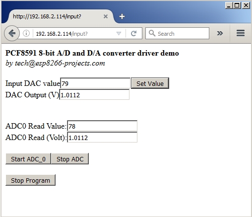
ESP Basic series - I2C driver example for the PCF8591 I2C 8-bit A/D and D/A converter. General view:
The PCF8591 is a single-chip, single-supply low-power 8-bit CMOS data acquisition device with four analog inputs, one analog output and a serial I2C-bus interface. Three address pins A0, A1 and A2 are used for programming the hardware address, allowing the use of up to eight devices connected to the I2C-bus without additional hardware. Address, control and data to and from the device are transferred serially via the two-line bidirectional I2C-bus.
The functions of the device include analog input multiplexing, on-chip track and hold function, 8-bit analog-to-digital conversion and an 8-bit digital-to-analog conversion. The maximum conversion rate is given by the maximum speed of the I2C-bus.
Features:
Single power supply
Operating supply voltage 2.5 V to 6.0 V
Low standby current
Serial input and output via I2C-bus
I2C address selection by 3 hardware address pins
Max sampling rate given by I2C-bus speed
4 analog inputs configurable as single ended or differential inputs
PCF8591 Module like the one from here or here, advertised as new versions.
For programming and uploading the driver and the software we will use the ESPBasic
Connection with the ESP8266 nEXT EVO Board is very easy, asPCF8591 Moduleconnector
is fully compatible with the nEXT Bus connector.
Driver implementation
As been a I2C compatible device you need to have a standard I2C Bus Initialisation function as usual and also to know the I2C address of the device.
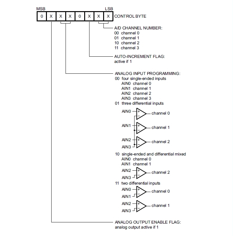
Control Byte is the second byte sent to a PCF8591 device and is stored in its control register and is required to control the device function :
Things to take care about:
The upper nibble of the control register is used for enabling the analog output, and for programming the analog inputs as single-ended or differential inputs. The lower nibble selects one of the analog input channels defined by the upper nibble .
If the auto-increment flag is set, the channel number is incremented automatically after each A/D conversion. If the auto-increment mode is desired in applications where the internal oscillator is used, the analog output enable flag must be set in the control byte (bit 6). This allows the internal oscillator to run continuously, by this means preventing conversion errors resulting from oscillator start-up delay.
The analog output enable flag can be reset at other times to reduce quiescent power consumption.
The selection of a non-existing input channel results in the highest available channel number being allocated. Therefore, if the auto-increment flag is set, the next selected channel is always channel 0.
The most significant bits of both nibbles are reserved for possible future functions and must be set to logic 0. After a Power-On Reset (POR) condition, all bits of the control register are reset to logic 0. The D/A converter and the oscillator are disabled for power saving. The analog output is switched to a high-impedance state.
Software:
1. Main program:
let address = 72 'PCF8591 I2C Address i2c.setup(4,5) 'choose your I2C bus pins cls let dac = 0 let dac_v = 0 let v_cal = 0.0128 wprint " <b>PCF8591 - 8-bit A/D and D/A converter driver <br>DAC demo</b><br><i>by tech@esp8266-projects.com</i><br><br> " wprint " Input DAC value" textbox dac button " Set Value ",[SetDAC] wprint " <br>DAC Output (V)" textbox dac_v wprint "<br><br>" button " Stop Program", [Exit] wait
In the ESP Basic Web editor interface Type & Save your program as "PCF8591.bas" and Run it.
If all OK the result should look as below:
If you want your program to start automatically at reboot/power ON then just Save it as "default.bas" and also from Settings Tab enable the "Run default.bas at startup".
Be aware that at start-up/reboot, it is a delay before your program will start automatically.
In the next part about PCF8591 we will talk about the ADC Driver implementation.