ESP8266 Projects Blog
Home of CBDB / MPDMv4 /SmartMon Development boards (ESP-12/ESP-07).
Guidelines and ESP8266 programming examples using LUA, Eclipse and Arduino IDE, ESP Basic and many more!
A fully isolated USB to Serial adapter for communication and
also programming devices protecting your USB ports and connected devices.
Integrated hardware Autoreset function makes it suitable for direct
programming ESP8266, ESP32 and other MCU's that require it.
If you use
Arduino IDE/Platformio/etc for example with ESP8266, you will love it,
as it doesn't need to press anymore RST/Prog buttons for new sketch
upload! The autoreset function takes care of that, putting automatically
the ESP8266 module in the right boot mode.
Youtube Video step-by-step Tutorial on how to use it to program a ESP8266 Module:
In the case above ESP8266 is embedded on a MPRSx8 Home Automation board but in the same easy way can be used for programming standalone ESP8266 modules.
Pinout
Capabilities
Fully isolated interface
High speed (can work OK also at 115200 and up - used it with Arduino IDE/Platfromio at 921600)
DTR/RTS/autoreset function
2.5 kV RMS integrated digital isolator from Silicon Labs
High electromagnetic immunity
Ultra low power
Schmitt trigger inputs
Transient Immunity 50 kV/μs
Schematics
USB interface
Digital isolator
Auto-reset circuit
Below you can find also the wiring for the MPRSx8 Home Automation Board Programming:
This is Part 4 of the SmartMon Extension Board series.
SmartMon v2.7ex Board is a extension
board fully compatible with Arduino, ESP8266, ARM, PIC & other
available MCu's out there. As long as your MCU/Dev Board has I2C Bus capabilities you are good to go!
It is probably one of the easiest ways to create your own Voltage/Current
and Power consumption monitoring system for your Projects, devices, batteries, power
supplies and many more!
UPDATE !! SmartMon v2.7Ex is available also on Tindie Store !
This time we will go thru a full example on how to monitor your power line and load, read
Voltage/Current and Power consumtion data and upload them on the
Thingspeak related Channel.
This is Part 3 of the SmartMon Extension Board series.
SmartMon v2.7ex Board is a extension
board fully compatible with Arduino, ESP8266, ARM, PIC & other
available MCu's out there. As long as your MCU/Dev Board has I2C Bus capabilities you are good to go!
It is probably one of the easiest ways to create your own Voltage/Current
and Power consumption monitoring system for your Projects, devices, batteries, power
supplies and many more!
UPDATE !! SmartMon v2.7Ex is available also on Tindie Store !
voltage = 0 current = 0 power = 0 peng = 0 eng = 0
2. I2C Init function
function init_i2c() i2c.setup(id, sda, scl, i2c.SLOW) end
3. INA219 Reset function
function reset() write_reg(0x00, 0xFFFF) end
4. Read register function
--read from reg_addr content of dev_addr function read_reg_str(reg_addr) i2c.start(id) i2c.address(id, devaddr, i2c.TRANSMITTER) i2c.write(id,reg_addr) i2c.stop(id) tmr.delay(1) i2c.start(id) i2c.address(id, devaddr, i2c.RECEIVER) c=i2c.read(id, 16) -- read 16bit val i2c.stop(id) return c end
5. Read register function - 16bit--returns 16 bit int
function read_reg_int(reg_addr) i2c.start(id) i2c.address(id, devaddr, i2c.TRANSMITTER) i2c.write(id,reg_addr) i2c.stop(id) tmr.delay(1) i2c.start(id) i2c.address(id, devaddr, i2c.RECEIVER) local c = i2c.read(id, 16) -- read 16bit val i2c.stop(id) --convert to 16 bit int local val = bit.lshift(string.byte(c, 1), 8) local val2 = bit.bor(val, string.byte(c, 2)) return val2 end
6. Write register function
function write_reg(reg_addr, reg_val) print("writing reg:" .. reg_addr .. ", reg_val:" .. reg_val) i2c.start(id) i2c.address(id, devaddr, i2c.TRANSMITTER) local bw = i2c.write(id, reg_addr) local bw2 = i2c.write(id, bit.rshift(reg_val, 8)) local bw3 = i2c.write(id, bit.band(reg_val, 0xFF)) i2c.stop(id) end
7. Calibration / settings function
function setCAL_reg() maxVoltage = 32 maxCurrentmA = 10000 write_reg(0x05,3950) --CALIBRATE FOR YOUR rshunt & stuff local config = 15391 write_reg(0x00, config) end
8. Read Current values (mA)
function getCurrent_mA() local valueInt = read_reg_int(0x04) return valueInt end
9. Read Bus Voltage (V)
function getBusVoltage_V() local valueInt = read_reg_int(0x02) -- Shift to the right 3 to drop CNVR and OVF and multiply by LSB = 4 local val2 = bit.rshift(valueInt, 3) local val2 = val2 * 4 return val2 * 0.001 end
10. Read Shunt resistor voltage drop (mV)
function getShuntVoltage_mV() -- Gets the raw shunt voltage (16-bit signed integer, so +-32767) local valueInt = read_reg_int(0x01) return valueInt * 0.01 end
11. Read Bus Power (W)
function getBusPowerWatts() local valueInt = read_reg_int(0x03) return valueInt*20*0.001 end
12. Print read values
function print_values() volt = getBusVoltage_V() print("\nVoltage : " .. volt.." V") current = getCurrent_mA()/1000 power = getBusPowerWatts() if (current > 65 ) then print("ERR 00.23") current = 0 power = 0 end eng = eng + power/60 print("Current : " .. string.format("%6.3f",current) .." A") print("Power : " .. power .." W\n") print("Energy : " .. string.format("%6.3f",eng) .." Wh\n") end
MAIN Program
---- INA216 Module TEST init_i2c() setCAL_reg() print_values()
If you want to read and update values every minute add function from below:
As this time we will talk about the Software side we will design a very simple driver for our board that will include also a interactive Web command interface for the MPRSx8 Home Automation Dev Board Relays.
To keep things simple, we will just add in our Web Interface 8 ON/OFF Buttons and one general OFF one, from where we can turn ON/OFF all the Relays switches.
i2c.begin(address) ss = 0 xor 255 'XOR - Bit masking for the desired I/O pins i2c.write(ss) i2c.end() button "x1", [5] ' Button for Relay 1 button "x2", [6] button "x3", [7] button "x4", [8] button "x5", [1] button "x6", [2] button "x7", [3] button "x8", [4] ' Button for Relay 8 button "OFF", [9] ' General OFF for all the Relays wait
2. General OFF for all the Relays subroutine
[9] i2c.begin(address) ss = 0 xor 255 'XOR - Bit masking for the desired I/O pins i2c.write(ss) i2c.end() wait
3. Subroutines for each Button
[1] i2c.begin(address) ss = ss xor 1 'XOR - Bit masking for the desired I/O pins i2c.write(ss) i2c.end() wait
[2] i2c.begin(address) ss = ss xor 2 i2c.write(ss) i2c.end() wait
[3] i2c.begin(address) ss = ss xor 4 i2c.write(ss) i2c.end() wait
[4] i2c.begin(address) ss = ss xor 8 i2c.write(ss) i2c.end() wait
[5] i2c.begin(address) ss = ss xor 16 i2c.write(ss) i2c.end() wait
[6] i2c.begin(address) ss = ss xor 32 i2c.write(ss) i2c.end() wait
[7] i2c.begin(address) ss = ss xor 64 i2c.write(ss) i2c.end() wait
[8] i2c.begin(address) ss = ss xor 128 i2c.write(ss) i2c.end() wait
In the Web editor interface Save your program as "test_MPRSx8_1.bas" and Run it.
If all OK the result should look as below:
If you want your program to start automatically at reboot/power ON then just Save it as "default.bas" and also from Settings Tab enable the "Run default.bas at startup".
Be aware that at start-up/reboot, it is a delay before your program will start automatically.
UPDATE !! SmartMon v2.7Ex is available also on Tindie Store !
This time we are exploring the Real Time Clock implementation and we will see how easy or complicated is to set & program the onboard RTC Clock.
And the story behind: For a complete monitoring/ data logging experience, a nice to have feature is a proper RTC clock. Having this in mind, for the new version of the SmartMon I choose to add it on-board for a very simple and easy integration in your related Voltage, Current, Power projects. The choosen one is the PCF8563 from NXP, a very nice and easy to program CMOS Real-Time Clock (RTC) and Calendar optimized for low power consumption.
A programmable clock output, interrupt output and voltage-low detector
are also provided. All addresses and data are transferred serially via a
two-line bidirectional I2C-bus with a maximum bus speed of 400 kbit/s.
Features:
• Provides year, month, day, weekday, hours, minutes, and seconds based on a
32.768 kHz quartz crystal • Century flag
• Clock operating voltage: 1.0 V to 5.5 V at room temperature
• Low backup current; typical 0.25uA at Vdd =3.0V and Tamb=25C
• 400 kHz two-wire I2C-bus interface (at VDD= 1.8 V to 5.5 V)
• Programmable clock output for peripheral devices (32.768 kHz, 1.024 kHz, 32 Hz, and 1Hz)
• Alarm and timer functions - separate Alarm triggered MOSFET output with separate voltage
input/supply included onboard, can direct drive upto 2A external devices, 3/5/12V
This time we are talking here about ESP8266/LUA driver but also Arduino implementation will follow.
If you use another ESP8266, or Arduino, ARM, PIC, whatever MCU you use there days for your projects, then just be sure that you are connecting the I2C lines (SDA/SCL) on the allocated pins for your setup. Driver implementation
As
PCF8563 has a I2C compatible compatible interface, driver building it
following more or less the same process as before for I2C devices. For more details about the RTC, please take a deeper look at the PCF8563 Datasheet and the related PCF8563 RTC clock driver Article.
1. Data conversion functions:
1.1 Decimal to BCD: function decToBcd(val) local d = string.format("%d",tonumber(val / 10)) local d1 = tonumber(d*10) local d2 = val - d1 return tonumber(d*16+d2) end
1.2 BCD to Decimal:
function bcdToDec(val) local hl=bit.rshift(val, 4) local hh=bit.band(val,0xf) local hr = string.format("%d%d", hl, hh) return string.format("%d%d", hl, hh) end 2. Init I2C bus/interface: address = 0x51, -- A2, A1, A0 = 0 id = 0 init = function (self, sda, scl) self.id = 0 i2c.setup(self.id, sda, scl, i2c.SLOW) end
For testing, pack it together and save the code on ESP as 'pcf8563.lua', restart ESP and run:
-- Set Initial Time and Date require('pcf8563') -- call for new created PCF8563 Module Driver sda, scl = 2, 1 -- declare your I2C interface PIN's pcf8563:init(sda, scl) -- initialize I2C Bus pcf8563:setTime(0,34,13,12,4,3,15) -- setTime(s,min,hour,day,weekday,month, year) -- get Time and Date require('pcf8563') sda, scl = 2, 1 pcf8563:init(sda, scl) s, m, h, d, dt, mn, y = pcf8563:readTime() --ReadTime function call =string.format("%s - %s/%s/20%s",dt, d, mn, y) =string.format(" %s:%s:%s", h, m, s)
Today we will start a new Battery Live Monitor System (BLMS) series related with the SmartMon v.2.7Ex Board.
SmartMonv2.7Ex board has been born as the next generation of BLMS,
bringing more flexibility and a lot of extra functionalities than the
previous one.
If you want to quickly add to your project Voltage, Current and Power monitoring capabilities, plus, as a bonus, a proper hardware RTC with integrated Alarm and Timer functions, this is the extension board that you was looking for.
The modular design will let you to easy connect it and use it with any MCU you want as long as it has I2C bus capabilities and is working in the 3-5.5V voltage range. That includes all the popular existing platforms like Arduino, PIC, ARM, Atmega, ESP8266 and many more!
TI INA219 integrated high-side current shunt and power monitor
High precision, high quality shunt resistor from BOURNS: very low Inductance (10nH) and Temperature Coeficient ( ±20 ppm/°C max.)
Measured Bus Current interval: 0-10A (standard) / 0-20A (optional)
High range Measured Bus Voltages from 0 to 26 V
Bus voltage is measured directly on the load side of the shunt resistor
SmartMon v.2.Ex Power supply voltage range - 3.3 to 5.5V
Standard I2C bus communication ( nEXT Bus connector)
PCF8563 RTC - real-time clock and calendar optimized for low power consumption
RTC Alarm and timer functions with MOSFET driven Interrupt output
On-board regulator option (can be populated and used it when you want to use the same main BUS Voltage input also as a power supply for the SmartMon Board)
Schematics:
High-side Voltage measurement, current shunt and power monitor
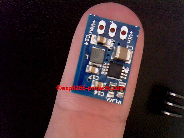
30V max Input, DC-DC High-Efficiency Step-down regulator, the
perfect drop-in replacement for standard Linear regulators:
LM7805,LM317 or similar.
And the story behind:
I was looking for a drop-in replacement for some standard linear
regulators in existing equipment that heats badly because of to small
heatsinks and some poor design.
Available space inside was way to small to install a bigger heatsink on
most boards.
Impressed by the results, have started using it almost everywhere
where I need a good Voltage Regulator, so ended up as a standard used
regulator module. If you need a nice and stable Voltage Regulator for
your projects, you might found it!
FEATURES:
Up to 95% Efficiency
Input Voltage Range: 4.4V to 30V
Output Voltage Range: 2.0V to 24V (changing the divider resistor, by default comes configured for 3.3 or 5V, as you choose)
Output Current - 0.65A max in actual configuration - upto 1A with extra cooling.
Automatic Pulse Frequency Modulation/Pulse-Width Modulation (PFM/PWM) Operation
WARNING!! You will play with LIVE MAINS!! Deadly zone!!
If you don't
have any experience and are not qualified for working with MAINS power I
will not encourage you to play arround!. The
author take no responsibility for any injury or
death resulting, directly or indirectly, from your inability to
appreciate the hazards of household mains voltages.
The circuit diagrams are as accurately as possible, but are offered with no
guarantees whatsoever.
There is no guarantee that this design meets any Rules which may be in
force in your country so please check before your local
rules/regulations.
For any new orders/requests please feel free to use as usual: tech (at) esp8266-projects.com. MPDMv4 Boards are also available on Tindie: AC MAINS Dimmer - MPDMv4
For today we have a short but comprehesive Tutorial on how to drive the MPDMv4 AC MAINS Dimmer board using the Arduino IDE:
Arduino IDE code example for the Youtube Video Tutorial:
/* Dimmer
Demonstrates the sending data from the computer to the Arduino board, in this case to control the brightness of MPDMv4 AC MAINS Dimmer. The data is sent in individual bytes, each of which ranges from 0 to 255. Arduino reads these bytes and uses them to set the VCNT brightness command .
The circuit: MPDMv4 Board attached from digital pin 3 to ground. Serial connection to Processing, Max/MSP, or another serial application
created 2006 by David A. Mellis modified 30 Aug 2011 by Tom Igoe and Scott Fitzgerald modified 14 Apr 2016 by TJ for esp8266-projects.com AC MAINS Power Dimmer MPDMv4 Driver This example code is in the public domain.
http://www.arduino.cc/en/Tutorial/Dimmer
*/
const int vcntPin = 3; // the pin that the MPDMv4 VCNT pin is attached to
void setup() { // initialize the serial communication: Serial.begin(9600); // initialize the VCNTPin as an output: pinMode(vcntPin, OUTPUT); // set default brightness value analogWrite(vcntPin, 230); }
void loop() { byte brightness;
// check if data has been sent from the computer: if (Serial.available()) { // read the most recent byte (which will be from 0 to 255): brightness = Serial.parseInt(); Serial.print("Command received : "); Serial.println(brightness); // set the brightness of the LED: analogWrite(vcntPin, brightness); } }