ESP8266 Projects Blog
Home of CBDB / MPDMv4 /SmartMon Development boards (ESP-12/ESP-07).
Guidelines and ESP8266 programming examples using LUA, Eclipse and Arduino IDE, ESP Basic and many more!
PCA9685-16Channel 12-bit PWM I²C-bus LED controller Driver - Part 1
If you are looking for a very simple to use 16 Channel LED controller or
just for a nice 16 Channel, high resolution PWM driver then this one is
for you!
The PCA9685 is an I²C-bus controlled 16-channel LED controller optimized for
Red/Green/Blue/Amber (RGBA) color backlighting applications.
Driver implementation As been a I2C compatible device you need to have a standard I2C Bus Initialisation function as usual and also to know the I2C address of the device. For a more detailed hardware overview go to PCA9685 General Description Article.
Software:
1. Main program:
i2c.setup(4,5) 'choose your I2C bus pins
dev_addr = 64 '0x40 - I2C Address for the PCA9685
mode1 = 0 '0x00 location for Mode1 register address mode2 = 1 '0x01 location for Mode2 reigster address led0 = 6 '0x06 location for start of LED0 registers rst = 1 '0x01 reset device rval = 0 'read register value
led_on = 4096 led_off = 0
ledN = 0
dim led_stat(8) led_stat(0)=0 led_stat(1)=0 led_stat(2)=0 led_stat(3)=0 led_stat(4)=0 led_stat(5)=0 led_stat(6)=0 led_stat(7)=0
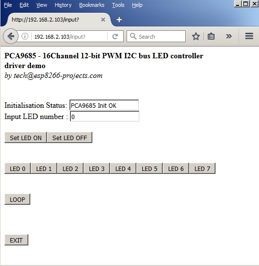
'check if proper initialised gosub [READ_REG] 'wprint rval if rval == "1" then status = true stat = "PCA9685 Init OK" else status = false stat = "PCA9685 Init Failure!" end if
wprint " <b>PCA9685 - 16Channel 12-bit PWM I2C bus LED controller<br>driver demo</b><br><i>by tech@esp8266-projects.com</i><br><br><br>" wprint "Initialisation Status: " textbox stat
'set for auto-increment let data = 160 gosub [WRITE_REG]
'Choose below the desired output mode! 'Direct LED connection 'set to output mode INVRT = 1 OUTDRV = 0 reg = mode2 data = 16 gosub [WRITE_REG]
'External N-type driver 'write_reg(mode2, 0x04) -- set to output mode INVRT = 0 OUTDRV = 1
The main goal of the project is to create a AC Mains Light dimmer that can automatically control the level of light and keep in in the desired set interval without any external intervention.
Why would you be intrested in such a setup? Well, if you have any interest in hydroponics, photography, or anywhere where you need some sort of constant flood light lamps with precise light intensitity level setup then might be a good idea to take a look :) What we will need:
BH1750FVI Module . Can be ordered in packs of ONE, FIVE or even TEN from the corresponding links. My 10 one was backordered but received it quite quickly.
For programming and uploading the driver and the software we will continue to use the LuaUploader as before.
Connection with the ESP8266 nEXT EVO Board is very easy, as MPU6050 GY-521 Module connector
is fully compatible with the nEXT Bus connector. Depending on how to you
choose you socket type, you can install it on TOP or Bottom of the ESP8266 nEXT EVO Board :
BH1750FVI Module directly connected to the ESP8266 nEXT EVO Board
And the whole project setup, with MPDVv4 AC Dimmer connected on ESP8266 GPIO13 (pin 7):
MPDM v4 + nEXT EVO + BH1750FVI
Closer look, MPDMv4 connected at ESP8266 GPIO13 (Pin7) for PWM control
function set_light() read_input(dev_addr) ll = light - hst --lower level lh = light + hst --upper level if (lux < ll) then p=0 i = i - step if (i<0) then i = 0 end pwm.setduty(7, i) end if (lux >lh) then p=0 i = i + step if (i>880) then i = 880 end pwm.setduty(7, i) end --print("Auto Level Adjust : "..i) --print(ll) --print(lh) if (ll< lux and lux < lh) then if (p<1) then p=1 end if (p<2) then print(string.format("\nLight Level: %0.2f lux",lux)) print("Auto Level Adjust : "..i) p=2 end end end
Main Program --PWM testing for MPDMv4 AC Dimmer Board
If you are looking for a very simple to use 16 Channel LED controller or just for a nice 16 Channel, high resolution PWM driver then this one is for you!
The PCA9685 is an I²C-bus controlled 16-channel LED controller optimized for
Red/Green/Blue/Amber (RGBA) color backlighting applications.
Each LED output has its
own 12-bit resolution (4096 steps) fixed frequency individual PWM controller that operates
at a programmable frequency from a typical of 24 Hz to 1526 Hz with a duty cycle that is
adjustable from 0 % to 100 % to allow the LED to be set to a specific brightness value.
All outputs are set to the same PWM frequency.
Each LED output can be off or on (no PWM control), or set at its individual PWM controller
value.
The LED output driver is programmed to be either open-drain with a 25 mA current
sink capability at 5 V or totem pole with a 25 mA sink, 10 mA source capability at 5 V.
The
PCA9685 operates with a supply voltage range of 2.3 V to 5.5 V and the inputs and
outputs are 5.5 V tolerant. LEDs can be directly connected to the LED output (up to
25 mA, 5.5 V) or controlled with external drivers and a minimum amount of discrete
components for larger current or higher voltage LEDs.
PCA9685 - Block Diagram
Features
16 LED drivers. Each output programmable at:
Off
On
Programmable LED brightness
Programmable LED turn-on time to help reduce EMI
1 MHz Fast-mode Plus compatible I²C-bus interface with 30 mA high drive capability
on SDA output for driving high capacitive buses
4096-step (12-bit) linear programmable brightness per LED output varying from fully
off (default) to maximum brightness
LED output frequency (all LEDs) typically varies from 24 Hz to 1526 Hz (Default of 1Eh
in PRE_SCALE register results in a 200 Hz refresh rate with oscillator clock of
25 MHz)
Sixteen totem pole outputs (sink 25 mA and source 10 mA at 5 V) with software
programmable open-drain LED outputs selection (default at totem pole). No input
function.
Output state change programmable on the Acknowledge or the STOP Command to
update outputs byte-by-byte or all at the same time (default to ‘Change on STOP’)
Active LOW Output Enable (OE) input pin. LEDn outputs programmable to logic 1,
logic 0 (default at power-up) or ‘high-impedance’ when OE is HIGH.
6 hardware address pins allow 62 PCA9685 devices to be connected to the same
I²C-bus
Toggling OE allows for hardware LED blinking
4 software programmable I²C-bus addresses (one LED All Call address and three LED
Sub Call addresses) allow groups of devices to be addressed at the same time in any
combination (for example, one register used for ‘All Call’ so that all the PCA9685s on
the I²C-bus can be addressed at the same time and the second register used for three
different addresses so that 1⁄3 of all devices on the bus can be addressed at the same
time in a group). Software enable and disable for these I²C-bus address.
Software Reset feature (SWRST General Call) allows the device to be reset through
the I²C-bus
25 MHz typical internal oscillator requires no external components
External 50 MHz (max.) clock input
Internal power-on reset
Noise filter on SDA/SCL inputs
Edge rate control on outputs
No output glitches on power-up
Supports hot insertion
Low standby current
Operating power supply voltage range of 2.3 V to 5.5 V
5.5 V tolerant inputs
-40 °C to +85 °C operation
ESD protection exceeds 2000 V HBM per JESD22-A114, 200 V MM per
JESD22-A115 and 1000 V CDM per JESD22-C101
Latch-up testing is done to JEDEC Standard JESD78 which exceeds 100 mA
For programming and uploading the driver and the software we will continue to use the LuaUploader as before.
Connection with the ESP8266 nEXT EVO Board is very easy, as PCA9685 Extension Board connector
is fully compatible with the nEXT connector. Depending on how to you
choose you socket type, you can install it on TOP or Bottom of the ESP8266 nEXT EVO Board :
PCA9685 16 Channel PWM Extension Board
Driver implementation As PCA9685 has a I2C compatible compatible interface, building a driver for it it's a pretty straigh forward process following the standard path for a I2C compatible device: 1 . I2C Bus initialisation function
function init_i2c(sda, scl) i2c.setup(id, sda, scl, i2c.SLOW) end
2 . PCA9685 Read register function
function read_reg(reg) i2c.start(id) i2c.address(id, dev_addr ,i2c.TRANSMITTER) i2c.write(id,reg) i2c.stop(id) i2c.start(0x0) i2c.address(0x0, dev_addr,i2c.RECEIVER) c = i2c.read(0x0,1) i2c.stop(0x0) rval = string.byte(c, 1) --print(rval) return rval end
3 . PCA9685 Write register function
function write_reg(reg, data) i2c.start(id) i2c.address(id, dev_addr ,i2c.TRANSMITTER) i2c.write(id,reg) i2c.write(id,data) i2c.stop(id) end
4 . Write 12bit values function
function write_12_bit(a) ah=bit.rshift(a,8) al=bit.band(a,0xff) --print(a,ah,al) return ah, al end
5 . PCA9685 initialisation function
-- LED_ON and LED_OFF are 12bit values (0-4095) -- ledN is 0-15
function init_pca() write_reg(mode1, rst) --reset device
if (read_reg(mode1)==0x01) then --check status status = true print("PCA9685 Init OK") else status = false print("PCA9685 Init Failure!") end --print(status)
write_reg(mode1, 0xA0) --10100000 - set for auto-increment -- choose here the desired output mode! --Direct LED connection write_reg(mode2, 0x10) --set to output mode INVRT = 1 OUTDRV = 0
--External N-type driver --write_reg(mode2, 0x04) -- set to output mode INVRT = 0 OUTDRV = 1
Somebody sent to me a nice & tiny temperature/humidity sensor breakout board based on the Si7021 IC:
Si7021 Module - Top View
On the Top side we have Si7021 Sensor only.
Si7021 Module - Bottom View
Bottom Side, a 3.3V LDO and a Voltage level shifting circuit that probably makes it 5V tolerant on I2C bus. We will use it at 3.3V so nothing to worry about.
DESCRIPTION
The Si7021 I2C Humidity and Temperature Sensor is a monolithic CMOS IC integrating humidity and temperature sensor elements, an analog-to-digital converter, signal processing, calibration data, and an I2C Interface.
The patented use of industry-standard, low-K polymeric dielectrics for sensing humidity enables the construction of low-power, monolithic CMOS Sensor ICs with low drift and hysteresis, and excellent long term stability.
The humidity and temperature sensors are factory-calibrated and the calibration data is stored in the on-chip non-volatile memory. This ensures that the sensors are fully interchangeable, with no recalibration or software changes required.
The Si7021 offers an accurate, low-power, factory-calibrated digital solution ideal for measuring humidity, dew-point, and temperature, in applications ranging from HVAC/R and asset tracking to industrial and consumer platforms.
Si7021 - Block Diagram
Nice. Looks more or less like SHT21 from Sensirion. And we will see that it is quite compatible (at least on the temp/humidity reading procedure side) with small differences for the rest of registers.
For programming and uploading the driver and the software we will continue to use the LuaUploader as before.
Connection with ESP8266 nEXT EVO Board is pretty straight-forward as the module is fully pin-to-pin compatible with the availavble nEXT Bus connector.
Si7021 Board connected with ESP8266 nEXT EVO DevBoard - TOP view
Si7021 Board connected with ESP8266 nEXT EVO DevBoard - 45 deg view
Software implementation
The Si7021 communicates with the host controller over a digital I2C interface. The 7-bit base slave address is 0x40
Master I2C devices communicate with the Si7021 using a command structure. The commands are listed below in the I2C command table. Commands other than those documented below are undefined and should not be sent to the device.
I2C Command Table
Issuing a Measurement Command The measurement commands instruct the Si7021 to perform one of two possible measurements: Relative Humidity or Temperature.
The procedure to issue any one of these commands is identical. While the measurement is in progress, the option of either clock stretching (Hold Master Mode) or Not Acknowledging read requests (No Hold Master Mode) is available to indicate to the master that the measurement is in progress. The chosen command code determines which mode is used.
Optionally, a checksum byte can be returned from the slave for use in checking for transmission errors. The checksum byte will follow the least significant measurement byte if it is acknowledged by the master. The checksum byte is not returned if the master “not acknowledges” the least significant measurement byte. The checksum byte is calculated using a CRC generator polynomial of x^8+ x^5 + x^4 + 1, with an initialization of 0x00.
The checksum byte is optional after initiating an RH or temperature measurement with commands 0xE5, 0xF5,0xE3, and 0xF3. It is required for reading the electronic ID with commands 0xFA 0x0F and 0xFC 0xC9.
For all other commands, the checksum byte is not supported.
1. Init I2C bus/interface
Standard I2C Bus Initialisation function:
function init_I2C() i2c.setup(bus, sda, scl, i2c.SLOW) end
2. Write Si7021 Register Function
write_Si_Reg = function (dev_addr, set) i2c.start(0x0) i2c.address(0x0, dev_addr ,i2c.TRANSMITTER) i2c.write(0x0,set) i2c.stop(0x0) tmr.delay(5000) end
3. Read Si7021 Register Function
read_Si_Reg = function (dev_addr) i2c.start(0x0) i2c.address(0x0, dev_addr,i2c.RECEIVER) tmr.delay(5000) c = i2c.read(0x0,2) i2c.stop(0x0)
rval = (bit.lshift(string.byte(c, 1), 8) + string.byte(c, 2)) status = bit.band(rval,3) --save status bits rval = bit.band(rval,65532) --clear status bits return rval, status end
4. Measuring Relative Humidity
Once a relative humidity measurement has been made, the results of the measurement may be converted to percent relative humidity by using the following expression:
hum = -6.0+125.0/65536.0*rval
A humidity measurement will always return XXXXXX10 in the LSB field -> Status bit = 1 -> marking a Humidity measurement data.
function read_hum() write_Si_Reg(dev_addr, RHumidityHoldCmd) tmr.delay(10000) read_Si_Reg(dev_addr) hum = -6.0+125.0/65536.0*rval print("\nStatus : "..status) print("Humidity : "..string.format("%.2f",hum).."%") end
5. Measuring Temperature
Each time a relative humidity measurement is made a temperature measurement is also made for the purposes of temperature compensation of the relative humidity measurement. If the temperature value is required, it can be read using command 0xE0; this avoids having to perform a second temperature measurement. The measure temperature commands 0xE3 and 0xF3 will perform a temperature measurement and return the measurement value, command 0xE0 does not perform a measurement but returns the temperature value measured during the relative humidity measurement. The checksum output is not available with the 0xE0 command.
The results of the temperature measurement may be converted to temperature in degrees Celsius (°C) using the following expression:
temp = -46.85+175.72/65536.0*rval
A temperature measurement will always return XXXXXX00 in the LSB field - Status bit = 0 -> marking a Temperature measurement data.
function read_temp() write_Si_Reg(dev_addr, TempHoldCmd) read_Si_Reg(dev_addr) temp = -46.85+175.72/65536.0*rval print("Status : "..status) print("Temperature : "..string.format("%.2f",temp).."C") end
As been requested by many people that have difficulties to use the
MPU6050 Modules, I've done a more detailed ESP8266 Video Tutorial
related with the MPU6050 GY-521 Module initialisation and basic usage.
It is a detailed, step-by-step tutorial, showing all the needed init stages and tests for a proper and smooth usage of the MPU6050 GY-521 module.
These ones seems to work OK connected directly to the 3.3V power on the ESP8266 nEXT EVO board Bus and looks to have some very low dropout voltage regulator. This are the good news about.
Now some bad news: it seems to be sold different types/flavours of modules (maybe old/new batches with various BOM) under the same name code so your experience may vary and might be necessary to use 5V power input for the GY-521. Or just bypass the Voltage Regulator to avoid any wiring around :).
MPU-60X0 Overview
The MPU-60X0 is the world’s first integrated 6-axis MotionTracking device that combines a 3-axis gyroscope, 3-axis accelerometer, and a Digital Motion Processor™ (DMP) all in a small 4x4x0.9mm package.
With its dedicated I2C sensor bus, it directly accepts inputs from an external 3-axis compass to provide a complete 9-axis MotionFusion™ output. It is also designed to interface with multiple non-inertial digital sensors, such as pressure sensors, on its auxiliary I2C port.
So, it can act as a I2C master for other I2C devices. That's cool!
For power supply flexibility, the MPU-60X0 operates from VDD power supply voltage range of 2.375V-3.46V. Additionally, the MPU-6050 provides a VLOGIC reference pin (in addition to its analog supply pin: VDD), which sets the logic levels of its I2C interface. The VLOGIC voltage may be 1.8V±5% or VDD.
The MPU-6000 and MPU-6050 are identical, except that the MPU-6050 supports the I2C serial interface only, and has a separate VLOGIC reference pin. The MPU-6000 supports both I2C and SPI interfaces and has a single supply pin, VDD, which is both the device’s logic reference supply and the analog supply for the part.
MPU-60X0 Features
1. Gyroscope Features
The triple-axis MEMS gyroscope in the MPU-60X0 includes a wide range of features:
Digital-output X-, Y-, and Z-Axis angular rate sensors (gyroscopes) with a user-programmable full-scale range of ±250, ±500, ±1000, and ±2000°/sec
External sync signal connected to the FSYNC pin supports image, video and GPS synchronization
Integrated 16-bit ADCs enable simultaneous sampling of gyros
Enhanced bias and sensitivity temperature stability reduces the need for user calibration
Improved low-frequency noise performance
Digitally-programmable low-pass filter
Gyroscope operating current: 3.6mA
Standby current: 5μA
Factory calibrated sensitivity scale factor
User self-test
2. Accelerometer Features
The triple-axis MEMS accelerometer in MPU-60X0 includes a wide range of features:
Digital-output triple-axis accelerometer with a programmable full scale range of ±2g, ±4g, ±8g and ±16g
Integrated 16-bit ADCs enable simultaneous sampling of accelerometers while requiring no external multiplexer
Accelerometer normal operating current: 500μA
Low power accelerometer mode current: 10μA at 1.25Hz, 20μA at 5Hz, 60μA at 20Hz, 110μA at 40Hz
Orientation detection and signaling
Tap detection
User-programmable interrupts
High-G interrupt
User self-test
3. Additional Features
The MPU-60X0 includes the following additional features:
9-Axis MotionFusion by the on-chip Digital Motion Processor (DMP)
Auxiliary master I2C bus for reading data from external sensors (e.g., magnetometer)
3.9mA operating current when all 6 motion sensing axes and the DMP are enabled
Smallest and thinnest QFN package for portable devices: 4x4x0.9mm
Minimal cross-axis sensitivity between the accelerometer and gyroscope axes
1024 byte FIFO buffer reduces power consumption by allowing host processor to read the data in bursts and then go into a low-power mode as the MPU collects more data
Digital-output temperature sensor
User-programmable digital filters for gyroscope, accelerometer, and temp sensor
10,000 g shock tolerant
400kHz Fast Mode I2C for communicating with all registers
1MHz SPI serial interface for communicating with all registers (MPU-6000 only)
20MHz SPI serial interface for reading sensor and interrupt registers (MPU-6000 only)
MEMS structure hermetically sealed and bonded at wafer level
RoHS and Green compliant
4. MotionProcessing
Internal Digital Motion Processing™ (DMP™) engine supports 3D MotionProcessing and gesture recognition algorithms
The MPU-60X0 collects gyroscope and accelerometer data while synchronizing data sampling at a user defined rate. The total dataset obtained by the MPU-60X0 includes 3-Axis gyroscope data, 3-Axis accelerometer data, and temperature data. The MPU’s calculated output to the system processor can also include heading data from a digital 3-axis third party magnetometer.
The FIFO buffers the complete data set, reducing timing requirements on the system processor by allowing the processor burst read the FIFO data. After burst reading the FIFO data, the system processor can save power by entering a low-power sleep mode while the MPU collects more data.
Programmable interrupt supports features such as gesture recognition, panning, zooming, scrolling, tap detection, and shake detection
Digitally-programmable low-pass filters
Low-power pedometer functionality allows the host processor to sleep while the DMP maintains the step count.
5.5 Clocking
On-chip timing generator ±1% frequency variation over full temperature range
Optional external clock inputs of 32.768kHz or 19.2MHz
It is quite a beast in a tiny package, with Gyroscope, Accelerometer, DMP and all the other goodies inside. For more details please take a look at the MPU60x0 Datasheet
For programming and uploading the driver and the software we will continue to use the LuaUploader as before.
Connection with the ESP8266 nEXT EVO Board is very easy, asMPU6050 GY-521 Moduleconnector
is fully compatible with the nEXT Bus connector. Depending on how to you
choose you socket type, you can install it on TOP or Bottom of the ESP8266 nEXT EVO Board :
MPU6050 GY-521 Module on top of the ESP8266 nEXT Evo Board
Driver implementation
1. Init I2C bus/interface
Standard I2C Bus Initialisation function:
function init_I2C() i2c.setup(bus, sda, scl, i2c.SLOW) end
2. READ MPU6050 Register
Before reading data from MPU6050, you must tell it which of its internal addresses you want to read
A read starts off by writing to the MPU6050
Procedure:
Send a start sequence.
Send I2C address of the device with the R/W bit low (i2c.TRANSMITTER)
Send the Internal register address
Stop sequence
Send a start sequence again (repeated start)
Send the I2C address of the device with the R/W bit high (i2c.RECEIVER)
Read data byte from the register
Send the stop sequence.
function read_reg_MPU(reg) i2c.start(bus) i2c.address(bus, dev_addr, i2c.TRANSMITTER) i2c.write(bus, reg) i2c.stop(bus) i2c.start(bus) i2c.address(bus, dev_addr, i2c.RECEIVER) c=i2c.read(bus, 1) i2c.stop(bus) --print(string.byte(c, 1)) return c end
3. WRITE MPU6050 Register
Procedure:
Send a start sequence
Send the I2C address of the MPU6050 with the R/W bit low (i2c.TRANSMITTER)
Send the internal register number you want to write to
Send the data byte
IF you want more data to be sent can be done here. MPU6050 will automatically increment the internal register address after each byte
Send the stop sequence.
function write_reg_MPU(reg,val) i2c.start(bus) i2c.address(bus, dev_addr, i2c.TRANSMITTER) i2c.write(bus, reg) i2c.write(bus, val) i2c.stop(bus) end
4. INIT MPU6050
When power up, MPU6050 will start in SLEEP mode. To be able to use it you need to START the device.
Procedure:
Set SLEEP bit = 0 in the Power Management Register (107) OR Clear the Register
function init_MPU(reg,val) --(107) 0x6B / 0 write_reg_MPU(reg,val) end
5. MPU6050 connectivity
MPU6050 connectivity status only!
Be sure that you have properly initialised I2C Bus before!
function status_MPU(dev_addr) i2c.start(bus) c=i2c.address(bus, dev_addr ,i2c.TRANSMITTER) i2c.stop(bus) if c==true then print(" Device found at address : "..string.format("0x%X",dev_addr)) else print("Device not found !!") end end
6. Check MPU6050 Status
Using the status_MPU() function and the Who Am I register to check if the MPU6050 is available and alive before doing anything else.
function check_MPU(dev_addr) print("") status_MPU(0x68) read_reg_MPU(117) --Register 117 – Who Am I - 0x75 if string.byte(c, 1)==104 then print(" MPU6050 Device answered OK!") else print(" Check Device - MPU6050 NOT available!") return end read_reg_MPU(107) --Register 107 – Power Management 1-0x6b if string.byte(c, 1)==64 then print(" MPU6050 in SLEEP Mode !") else print(" MPU6050 in ACTIVE Mode !") end end
7. READ MPU6050 RAW DATA
Reading RAW data from the MPU6050. No conversion or transformation si done.
Received Data is in 2 complement format.
Procedure:
Send a start sequence.
Send I2C address of the device with the R/W bit low (i2c.TRANSMITTER)
Send the Internal register address
Stop sequence
Send a start sequence again (repeated start)
Send the I2C address of the device with the R/W bit high (i2c.RECEIVER)
Read the number of the requested data bytes from the registers