Showing posts with label PWM. Show all posts

Friday, November 25, 2016

ESP Basic - PCA9685-16Channel 12-bit PWM I²C-bus LED controller Driver - Part 1


PCA9685 Extension Board Module Available also on Tindie!


ESP Basic Tutorials Series: 

 PCA9685-16Channel 12-bit PWM I²C-bus LED controller Driver - Part 1

  If you are looking for a very simple to use 16 Channel LED controller or just for a nice 16 Channel, high resolution PWM driver then this one is for you!

   The PCA9685 is an I²C-bus controlled 16-channel LED controller optimized for Red/Green/Blue/Amber (RGBA) color backlighting applications.


 What we will need:

    Connection with the ESP8266 nEXT EVO Board is very easy, as PCA9685 Module connector is fully compatible with the nEXT Bus connector.


Driver implementation

   As been a I2C compatible device you need to have a standard I2C Bus Initialisation function as usual and also to know the I2C address of the device.  
  For a more detailed hardware overview go to PCA9685 General Description Article. 


 Software: 

1. Main program:

 i2c.setup(4,5) 'choose your I2C bus pins

dev_addr = 64  '0x40 - I2C Address for the PCA9685

mode1 = 0    '0x00 location for Mode1 register address
mode2 = 1    '0x01 location for Mode2 reigster address
led0 = 6     '0x06 location for start of LED0 registers
rst = 1      '0x01 reset device
rval = 0     'read register value

led_on = 4096
led_off = 0

ledN = 0

dim led_stat(8)
led_stat(0)=0
led_stat(1)=0
led_stat(2)=0
led_stat(3)=0
led_stat(4)=0
led_stat(5)=0
led_stat(6)=0
led_stat(7)=0


stat = "Init.."

'reset device     write_reg(mode1, rst)
reg = mode1
data = rst
gosub [WRITE_REG]

'check if proper initialised
gosub [READ_REG]
'wprint rval
if rval == "1" then
   status = true
   stat = "PCA9685 Init OK"
else
   status = false
   stat = "PCA9685 Init Failure!"
end if

wprint " <b>PCA9685 - 16Channel 12-bit PWM I2C bus LED controller<br>driver demo</b><br><i>by tech@esp8266-projects.com</i><br><br><br>"
wprint "Initialisation Status: "
textbox stat

'set for auto-increment
let data = 160
gosub [WRITE_REG]

'Choose below the desired output mode!
'Direct LED connection
'set to output mode INVRT = 1 OUTDRV = 0
reg = mode2
data = 16
gosub [WRITE_REG]


'External N-type driver
'write_reg(mode2, 0x04)   -- set to output mode INVRT = 0 OUTDRV = 1

'External P-type driver
'write_reg(mode2, 0x14) --set to output mode INVRT = 1 OUTDRV = 1
 
'choose LED_N - ON
wprint " <br>Input LED number : "
textbox ledN
wprint "<br> <br>"
button " Set LED ON ",[SetON]
button " Set LED OFF ",[SetOFF]
wprint "<br> <br> <br>"
button "LED 0",[LED0]
button "LED 1",[LED1]
button "LED 2",[LED2]
button "LED 3",[LED3]
button "LED 4",[LED4]
button "LED 5",[LED5]
button "LED 6",[LED6]
button "LED 7",[LED7]
wprint "<br> <br><br>"
button "LOOP",[loop]
wprint "<br> <br><br> <br>"
button "EXIT",[Exit]
wait


2. LOW Level subroutines


2.1 WRITE Register "reg"

[WRITE_REG]
i2c.begin(dev_addr)
i2c.write(reg)
i2c.write(data)
i2c.end()
return

2.2 READ Register "reg"


[READ_REG]
i2c.begin(dev_addr)
i2c.write(reg)
i2c.end()
i2c.begin(dev_addr)
i2c.requestfrom(dev_addr,1) 'start a transaction to read 1 byte
rval = i2c.read()           'read the byte
i2c.end()
return


2.3 WRITE LED_N Register
 

[WRITE_LED]
i2c.begin(dev_addr)
i2c.write(led0+4*ledN)
ah = led_on >> 8
al = led_on and 255
i2c.write(al)
i2c.write(ah)

ah = led_off >> 8
al = led_off and 255
i2c.write(al)
i2c.write(ah)
i2c.end()
return


 3. BUTTON Subroutines

[LED0]
ledN = 0
gosub [LED_SW]
wait

[LED1]
ledN = 1
gosub [LED_SW]
wait

[LED2]
ledN = 2
gosub [LED_SW]
wait

[LED3]
ledN = 3
gosub [LED_SW]
wait

[LED4]
ledN = 4
gosub [LED_SW]
wait

[LED5]
ledN = 5
gosub [LED_SW]
wait

[LED6]
ledN = 6
gosub [LED_SW]
wait

[LED7]
ledN = 7
gosub [LED_SW]
wait


4. LED_N Switch subroutine


[LED_SW]
if led_stat(ledN) = 0 then
   led_stat(ledN) = 1
   led_on = 4096
   led_off = 0
   gosub [WRITE_LED]
else
   led_stat(ledN) = 0
   led_on = 0
   led_off = 4096
   gosub [WRITE_LED]
end if
return


5. ON / OFF Subroutines

          [SetON]
led_on = 4096
led_off = 0
gosub [WRITE_LED]
wait

[SetOFF]
led_on = 0
led_off = 4096
gosub [WRITE_LED]
wait


6. FOR loop demo
[loop]
For x = 0 to 8
ledN = x
gosub [LED_SW]
Next x
For x = 8 to 0 step -1
ledN = x
gosub [LED_SW]
Next x
wait


7. EXIT Program subroutine

[Exit]
end


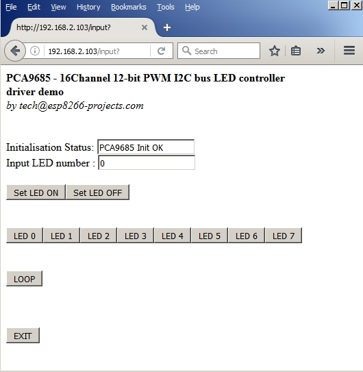
In the ESP Basic Web editor interface Type & Save your program as "PCA9685.bas" and Run it.  
If all OK the result should look as below:


Saturday, July 30, 2016

AC PWM Dimmer with Light Sensor


//YOUTUBE VIDEO HERE//

You can see this article as a continuation of the previous BH1750FVI - I2C Light Sensor Driver one.

    The main goal of the project is to create a AC Mains Light dimmer that can automatically control the level of light and keep in in the desired set interval without any external intervention.

   Why would you be intrested in such a setup? Well, if you have any interest in hydroponics, photography, or anywhere where you need some sort of constant flood light lamps with precise light intensitity level setup then might be a good idea to take a look :)


What we will need:


     Connection with the ESP8266 nEXT EVO Board is very easy, as MPU6050 GY-521 Module connector is fully compatible with the nEXT Bus connector. Depending on how to you choose you socket type, you can install it on TOP or Bottom of the ESP8266 nEXT EVO Board :


BH1750FVI Module directly connected to the ESP8266 nEXT EVO Board


And the whole project setup, with MPDVv4 AC Dimmer connected on ESP8266 GPIO13 (pin 7):

 
MPDM v4 + nEXT EVO + BH1750FVI


Closer look, MPDMv4 connected at ESP8266 GPIO13 (Pin7) for PWM control


Software implementation

You will need also the code from the previous BH1750FVI article. Please take also a look there for more details.


1. Ligth level auto-adjust function

 function set_light()
    read_input(dev_addr)
    ll = light - hst    --lower level
    lh = light + hst    --upper level
    if (lux < ll) then
       p=0
       i = i - step
       if (i<0) then i = 0
       end
       pwm.setduty(7, i)    
    end
    if (lux >lh) then
       p=0
       i = i + step
       if (i>880) then i = 880
       end
       pwm.setduty(7, i)    
    end
    --print("Auto Level Adjust : "..i)
    --print(ll)
    --print(lh)
    if (ll< lux and lux < lh) then
      if (p<1) then p=1
      end
      if (p<2) then
         print(string.format("\nLight Level: %0.2f lux",lux))
         print("Auto Level Adjust : "..i)
         p=2
      end
    end
end


Main Program
 
--PWM testing for MPDMv4 AC Dimmer Board
 

pwm.setup(7, 500, 850)    --MPDMv4 control pin
i=10                                  --initial Light Level

pwm.setduty(7, i)             --set initial ligfht level

light = 250                       --light level
hst = 40                            --histeresis coef for desired light interval
step = 1                            --light step
p=0         
 

--read light intensity value every 50 and autoadjust Light Dimmer Driver accordingly
tmr.alarm( 1, 50, 1, function()
  set_light()
end)


Wednesday, June 29, 2016

PCA9685-16Channel 12-bit PWM I²C-bus LED controller Driver


    !! UPDATE !! UPDATE !!
   Available on Tindie Store here 


   PCA9685 General Description

   If you are looking for a very simple to use 16 Channel LED controller or just for a nice 16 Channel, high resolution PWM driver then this one is for you!

   The PCA9685 is an I²C-bus controlled 16-channel LED controller optimized for Red/Green/Blue/Amber (RGBA) color backlighting applications.

   Each LED output has its own 12-bit resolution (4096 steps) fixed frequency individual PWM controller that operates at a programmable frequency from a typical of 24 Hz to 1526 Hz with a duty cycle that is adjustable from 0 % to 100 % to allow the LED to be set to a specific brightness value. All outputs are set to the same PWM frequency.

  Each LED output can be off or on (no PWM control), or set at its individual PWM controller value.

  The LED output driver is programmed to be either open-drain with a 25 mA current sink capability at 5 V or totem pole with a 25 mA sink, 10 mA source capability at 5 V.

  The PCA9685 operates with a supply voltage range of 2.3 V to 5.5 V and the inputs and outputs are 5.5 V tolerant. LEDs can be directly connected to the LED output (up to 25 mA, 5.5 V) or controlled with external drivers and a minimum amount of discrete components for larger current or higher voltage LEDs.


PCA9685 - Block Diagram


Features

  • 16 LED drivers. Each output programmable at:
    • Off
    • On
    • Programmable LED brightness
    • Programmable LED turn-on time to help reduce EMI
     
  • 1 MHz Fast-mode Plus compatible I²C-bus interface with 30 mA high drive capability on SDA output for driving high capacitive buses 
  • 4096-step (12-bit) linear programmable brightness per LED output varying from fully off (default) to maximum brightness 
  • LED output frequency (all LEDs) typically varies from 24 Hz to 1526 Hz (Default of 1Eh in PRE_SCALE register results in a 200 Hz refresh rate with oscillator clock of 25 MHz)
  • Sixteen totem pole outputs (sink 25 mA and source 10 mA at 5 V) with software programmable open-drain LED outputs selection (default at totem pole). No input function.
  • Output state change programmable on the Acknowledge or the STOP Command to update outputs byte-by-byte or all at the same time (default to ‘Change on STOP’)
  • Active LOW Output Enable (OE) input pin. LEDn outputs programmable to logic 1, logic 0 (default at power-up) or ‘high-impedance’ when OE is HIGH.
  • 6 hardware address pins allow 62 PCA9685 devices to be connected to the same I²C-bus
  • Toggling OE allows for hardware LED blinking
  • 4 software programmable I²C-bus addresses (one LED All Call address and three LED Sub Call addresses) allow groups of devices to be addressed at the same time in any combination (for example, one register used for ‘All Call’ so that all the PCA9685s on the I²C-bus can be addressed at the same time and the second register used for three different addresses so that 1⁄3 of all devices on the bus can be addressed at the same time in a group). Software enable and disable for these I²C-bus address.
  • Software Reset feature (SWRST General Call) allows the device to be reset through the I²C-bus
  • 25 MHz typical internal oscillator requires no external components
  • External 50 MHz (max.) clock input
  • Internal power-on reset
  • Noise filter on SDA/SCL inputs
  • Edge rate control on outputs
  • No output glitches on power-up
  • Supports hot insertion
  • Low standby current
  • Operating power supply voltage range of 2.3 V to 5.5 V
  • 5.5 V tolerant inputs
  • -40 °C to +85 °C operation
  • ESD protection exceeds 2000 V HBM per JESD22-A114, 200 V MM per JESD22-A115 and 1000 V CDM per JESD22-C101
  • Latch-up testing is done to JEDEC Standard JESD78 which exceeds 100 mA
  • Packages offered: TSSOP28, HVQFN28


 For more details please take a look at the PCA9685 Datasheet


What we will need:

  • ESP8266 nEXT EVO Board
  • PCA9685 Extension Board as below or similar
  • For programming and uploading the driver and the software we will continue to use the LuaUploader as before.  
    Connection with the ESP8266 nEXT EVO Board is very easy, as PCA9685 Extension Board connector is fully compatible with the nEXT connector. Depending on how to you choose you socket type, you can install it on TOP or Bottom of the ESP8266 nEXT EVO Board :

PCA9685 16 Channel PWM Extension Board


Driver implementation
 
 
As
PCA9685 has a I2C compatible compatible interface, building a driver for it it's a pretty straigh forward process following the standard path for a I2C compatible device:
 
 
1 . I2C Bus initialisation function
function  init_i2c(sda, scl)
          i2c.setup(id, sda, scl, i2c.SLOW)
     end


2 . PCA9685 Read register function
function read_reg(reg)
          i2c.start(id)
          i2c.address(id, dev_addr ,i2c.TRANSMITTER)
          i2c.write(id,reg)
          i2c.stop(id)
          i2c.start(0x0)
          i2c.address(0x0, dev_addr,i2c.RECEIVER)
          c = i2c.read(0x0,1)
          i2c.stop(0x0)
          rval = string.byte(c, 1)
          --print(rval)
          return rval
end

3 . PCA9685 Write register function
function write_reg(reg, data)
          i2c.start(id)
          i2c.address(id, dev_addr ,i2c.TRANSMITTER)
          i2c.write(id,reg)
          i2c.write(id,data)
          i2c.stop(id)
end


4 . Write 12bit values function
function write_12_bit(a)
         ah=bit.rshift(a,8)
         al=bit.band(a,0xff)
         --print(a,ah,al)
         return ah, al
end  

5 . PCA9685 initialisation function

-- LED_ON and LED_OFF are 12bit values (0-4095)
-- ledN is 0-15

function init_pca()
    write_reg(mode1, rst)           --reset device

    if (read_reg(mode1)==0x01) then --check status
        status = true
        print("PCA9685 Init OK")
    else
        status = false
        print("PCA9685 Init Failure!")
    end
    --print(status)

    write_reg(mode1, 0xA0) --10100000 - set for auto-increment


   -- choose here the desired output mode!

    --Direct LED connection
    write_reg(mode2, 0x10) --set to output mode INVRT = 1 OUTDRV = 0

    --External N-type driver
    --write_reg(mode2, 0x04)   -- set to output mode INVRT = 0 OUTDRV = 1

    --External P-type driver
    --write_reg(mode2, 0x14) --set to output mode INVRT = 1 OUTDRV = 1
   
    return status
end


6 . Write LEDn function
 function write_LED(ledN, LED_ON, LED_OFF)
          i2c.start(id)
          i2c.address(id, dev_addr ,i2c.TRANSMITTER)
          i2c.write(id,led0+4*ledN)
          write_12_bit(LED_ON)
          i2c.write(id,al)
          i2c.write(id,ah)
          write_12_bit(LED_OFF)
          i2c.write(id,al)
          i2c.write(id,ah)
          i2c.stop(id)
end


7 . Set LEDn ON function  

function setLED_ON(ledN)
        write_LED(ledN,0x1000,0)
end


8 . Set LEDn OFF function

function setLED_OFF(ledN)
        write_LED(ledN,0,0x1000)
end


9 . Set LEDn Dimmer function

function LED_Dimmer(ledN, dimm)
   if (dimm==0) then setLED_OFF(ledN)
   else if (dimm==100) then setLED_ON(ledN)
        else write_LED(ledN, dim, 0)
   end
   end
end


 10 . Main Program
dev_addr=0x40  --I2C Address for the PCA9685

mode1=0x00     --location for Mode1 register address
mode2=0x01     --location for Mode2 reigster address
led0=0x06      --location for start of LED0 registers
rst=0x01       --reset device

id = 0
sda=2 --GPIO4
scl=1 --GPIO5

--init I2C Bus
init_i2c(sda, scl)


--init PCA9685
init_pca()
 
--running tests
--set LED_0 ON/OFF
setLED_ON(0)
setLED_OFF(0)

--Dim LED_0 at different levels
write_LED(0,0,4095)
write_LED(0,0,2048)
write_LED(0,0,1024)
write_LED(0,0,512)
write_LED(0,0,256)
write_LED(0,0,128)
write_LED(0,0,64)
write_LED(0,0,32)
write_LED(0,0,16)
write_LED(0,0,8)
write_LED(0,0,4)

 --test Dimmer
dim=2
tmr.alarm( 1, 200, 1, function()
      if (dim>=4096) then dim=2 end
      write_LED(0,0,dim)
      dim=dim+200
      print(dim)
end)


tmr.stop(1)