Thursday, February 26, 2015

PART3 - I2C Driver - MCP9808 - Temperature Logger - ESP8266 CBDB

  As it was requested from you, my readers, in Part 3  of our CBDB saga, we will start building a simple, high precision, Temperature Data logger based on the MCP9808 chip, a ±0.5°C Maximum Accuracy Digital Temperature Sensor. As far as I know this is the first time NodeMCU float version I2C Driver for MCP9808.


     Features
     • Accuracy:
        - ±0.25 (typical) from -40°C to +125°C
       - ±0.5°C (maximum) from -20°C to 100°C
       - ±1°C (maximum) from -40°C to +125°C
  • User-Selectable Measurement Resolution:
       - +0.5°C, +0.25°C, +0.125°C, +0.0625°C
  • User-Programmable Temperature Limits:
       - Temperature Window Limit
       - Critical Temperature Limit
   • User-Programmable Temperature Alert Output
    • Operating Voltage Range: 2.7V to 5.5V
    • Operating Current: 200 μA (typical)
    • Shutdown Current: 0.1 μA (typical)
   • 2-wire Interface: I2C/SMBus Compatible
    • Available Packages: 2x3 DFN-8, MSOP-8

For more details, please see MCP9008 Datasheet

Don't be scared by the MSOP-8 package, with a small MSOP to DIP adapter will fit great in our CBDB extension slots it will not matter at all.

MSSOP8-DIP8 package adapter
 
What we will need:
  • CBDB Board
  • USB adapter (take a look on Part 1 for details how to connect them together)
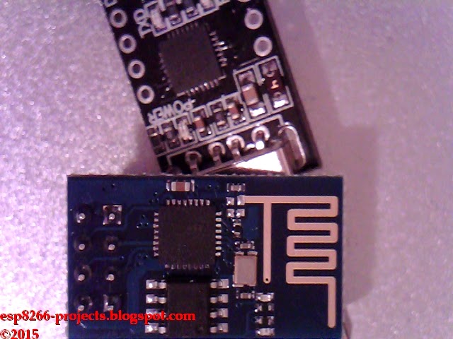
  • MCP9808 Module from above
  • LED module (if you want maybe a LED ticker)

CBDB with MCP9808 Temperture module
CBDB with MCP9808 Temperature module + LED ticker

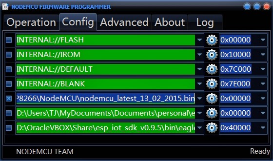
For programming and uploading the driver and the software we will continue to use the LuaUploader as before.

Driver implementation.

As MCP9808 has a I2C compatible compatible interface, building a driver for it it's a pretty straigh forward process:

1. Init I2C bus/interface
     
          dev_addr = 0x1F,
          init = function (self, sda, scl)
                   self.id = 0
           i2c.setup(self.id, sda, scl, i2c.SLOW)
          end


2. Read / Write to/from the desired register location.
  •  READ Register function
     read_reg = function(self, dev_addr, reg_addr)
          i2c.start(self.id)
          i2c.address(self.id, dev_addr ,i2c.TRANSMITTER)
          i2c.write(self.id,reg_addr)
          i2c.stop(self.id)
          i2c.start(self.id)
          i2c.address(self.id, dev_addr,i2c.RECEIVER)
          c=i2c.read(self.id,2)
          i2c.stop(self.id)
          return c
    end

  • READ Temperature function
    readTemp = function(self)
            h, l = string.byte(self:read_reg(0x1F, 0x05), 1, 2)
            h1=bit.band(h,0x1F)
            --check if Ta > 0C or Ta<0C
            Sgn = bit.band(h,0x10)             
            -- transform - CLEAR Sing BIT if Ta < 0C
            h2 = bit.band(h1,0x0F)
            tp = h2*16+l/16
            --END calculate temperature for Ta > 0
           return tp
    end


NOTE: This is for Tambient > 0°C only. Take a look in the  MCP9008 Datasheet . If you need it also on the negative temperature scale then you need to do some extra transformations as the temperature data is stored in the 16-bit read-only Ambient Temperature register Ta as 13-bit data in two’s complement format.

For testing, just save the code on ESP as 'mcp9808.lua', restart ESP and run:
           require('mcp9808')                 --call for new created MCP9808 Module Driver
           sda=2 --GPIO4                      --  declare your I2C interface PIN's
           scl=1 --GPIO5
          mcp9808:init(sda, scl)            -- initialize I2C    
          tp1 = mcp9808:readTemp()   -- read temperature
         =print(tp1)                              -- print it

 Let's put it together :

If all ok, we can move to the next step, how to make the data available on the web. 
For this one we will need 
WEB Server 
srv=net.createServer(net.TCP)
  srv:listen(80,
     function(conn)
           conn:on("receive",function(conn,payload) print(payload)
           conn:send("HTTP/1.1 200 OK\n\n")
           conn:send("<META HTTP-EQUIV=\"REFRESH\" CONTENT=\"5\">")
           conn:send("<html><title>MCP9808 - Temperature Log Server - ESP8266</title><body>")
           conn:send("<h1>ESP8266 Temperature Log Server - MCP9808</h1><BR>")
           conn:send("Temperature   : <b>" .. tp1 .. "&deg;C</b><BR><BR>")
           conn:send("Node.HEAP : <b>" .. node.heap() .. "</b><BR><BR>")
           conn:send("IP ADDR    : <b>".. wifi.sta.getip() .. "</b><BR>")
           conn:send("Node MAC   : <b>" .. wifi.sta.getmac() .. "</b><br>")
           conn:send("TMR.NOW    : <b>" .. tmr.now() .. "</b><BR<BR><BR>")
           conn:send("</html></body>")
           conn:on("sent",function(conn) conn:close() end)
      end)
end)
 READ Temperature function
        function readTMP()
            mcp9808:init(sda, scl)
            tp1 = mcp9808:readTemp()
            print(tp1)
        end

TIMER to establish how often we want the reading process to be done.
       -- read data every 1sec for direct web reading
       tmr.alarm(0, 1000, 1, function() readTMP() end )

 Save the code on ESP as 'web_temp.lua', restart ESP and run:  
        
        =wifi.sta.getip()              -- find the IP Address where your Web Server will be
        dofile("web_temp.lua")  -- Start the Web Server

 Open your favorite Web browser and type your nre Web Server IP address. If all ok, should look something like below :


So far so good. Next if you want the Web Server to start automatically when your CBDB module starts or reboots, then you neet to create and add some lines in your 'init.lua' file:

tmr.now()                         -- for debug only, you can skip it
wifi.sta.getmac()     
        -- for debug only, you can skip it       
wifi.sta.getip()
                -- for debug only, you can skip itnode.heap()
dofile("web_temp.lua")   -- needed to start Web Server and  Temperature logger


Save the code on ESP as 'init.lua', restart ESP. It should reboot and restart the program and reinitialize the Web Server.


That's all for today, thank you for your great feedback and looking forward for your suggestions!

Tuesday, February 24, 2015

PART2 - Programming Firmware - NodeMCU - ESP8266 - Breadboard Time - Cheap and dirty basic development board (CBDB)

   Part 2 of the the long awaited CBDB Series :)

    This time we will talk about how to reflash your ESP Module with a different firmware and how can be done using a CBDB setup, easy as "just insert a yellow jumper" story.


   As you remember from the previous part, the ESP-07 module that I have received was already programmed with the AT firmware. Great piece of code, indeed, but I really think a more flexible and standalone mode of usage will go better with out CBDB Setup. You will be amazed what kind of applications can be done using CBDB only and how easy has become in the IOT world this days. I remember doing someting similar 15 years ago ... you don't want to know the complexity and the cost just to turn On/Off via Internet some remote Power Sockets.

    For this reasons we will use for further projects, examples and tests, NodeMCU, a LUA based interpreter that runs directly on ESP8266. What that mens? Means a flexible language, event-driven advanced API for hardware IO and network applications, standalone operation of the ESP module, the "bread-and-butter" thing that was missing to our "ghetto-style" setup :).

What we will use in this process:
  • CBDB board (As prepared in the previuos part)
  • USB adapter (take a look on Part 1 for details how to connect them together)
  • NodeMCU firmware (download latest - it's the floating point version for now)
  • NodeMCU Flasher ( firmware programmer for NodeMCU DEVKIT)
    Now, few words about NodeMCU Flasher: It's  doing a great the job, exactly in the spirit of our CBDB setup, easy, cheap and dirty.

BUT take a look to my previous post about NodeMCU Flasher. It's some sort of price that you will pay. Keep in mind that you have the source available. Open "UnitFormMain.pas" file and search for "www.vowstar.com/lambdadriver/". Now it's at line 959. Might vary in the future.

   If you don't like the fact that is trying to access Internet, just remove from code related lines and recompile OR quick-and-dirty style, just block NodeMCU Flasher program from your computer Firewall for any outgoing trafffic. You are keeping full control of your Outgoing traffic from your Computer, don't ya? :)

<paranoia mode on>I don't want my fridge to start speaking with chinese girls without my knowledge. Any girls, to be politically correct. Or boys. Even more correct. lol. </paranoia mode>

With all the pieces in place, flashing the module is straings away:
  • connect CBDB Module with the USB Adapter, Set the PROG jumper in the Programming mode position (closed) and power on

  • start NodeMCU Flasher. Choose you USB adapter corresponding port 

  • add from Config Menu latest previously downloaded firmware. It must start from 0x0000. Disable anything else. 
  • Go back on Operation tab. Power off your CBDB Module. Press FLASH Button. power ON quick CBDB module. It will be recognised and will start flashing. Give it a second try if necessary.
  • When finished succesfully A green OK checkmark will appear


    Power Off CBDB Module, Remove yellow jumper. Power back ON. You are the proud owner of a NodeMCU programmed module.
   Now let's test it. Open your favorite Serial Terminal Program. Choose the corresponding port. Connect. Reboot CBDB module. The new NodeMCU boot message will apear. Try "AT+RST" command. Observe the answer this time.


   For further programming in LUA, it might be possible to do it directly in your Serial Terminal Program but I will recomend you to use a more dedicated program for that, like LuaLoader or LuaUploader. I will stay with the latest one, for it's great flexibility and simplicity.

This is how it looks when opening LuaUploader and reset your CBDB Board
 To run quick a test, just use the code snippets provided by LuaUploader at start-up. Select the piece of code that you want to run and press "Execute Selection" button.
  • To quick setup your WIFI network :
-- One time ESP Setup --
wifi.setmode(wifi.STATION)
wifi.sta.config ( "YOUR_WIFI_SSID" , "PASSWORD" ) 
print(wifi.sta.getip())

  • For the Blinky test, just use a prepared LED as in the picture, insert it on yellow jumper place and run de modified code from below
Please check Anode/Catode of the LED
   -- Blink using timer alarm --
   timerId = 0 -- we have seven timers! 0..6
   dly = 500 -- milliseconds
   ledPin = 3 -- 3=GPIO0
   gpio.mode(ledPin,gpio.OUTPUT)
   ledState = 0
   tmr.alarm( timerId, dly, 1, function()
        ledState = 1 - ledState;
        gpio.write(ledPin, ledState)
   end)

Select the Blinky piece of code that you want to run and press "Execute Selection" button.

Next time we will move further in the LUA World with more ESP8266 Projects! A whole world of interesting stuff will follow.

Saturday, February 21, 2015

ESP8266 - NodeMCU Flasher PROBLEM? - Calling back home??

    I was dowloading this morning the NodeMCU Flasher program from https://github.com/nodemcu/nodemcu-flasher. This is the official firmware programmer for NodeMCU DEVKIT V0.9.

    Has anybody any idea why is it trying to connect at startup over the internet at the address below?


Am I missing something maybe? :)

Friday, February 20, 2015

ESP8266 - Breadboard Time - Cheap and dirty basic development board (CBDB) !!


   I was in the process of preparing a post about how to easy breadboard ESP-01 modules but meanwhile I have received the new ESP-07 variant.

ESP-07 Module
ESP-07 Pinout


   After the initial frustration with ESP-07 and after repairing it as explained in the previous post, I have decided that it will more interesting to use this one for the projects (more GPIO lines, easier deep-sleep thru GPIO16, ADC pin, 4M flash). Indeed, they are 2mm pin spacing, so is not breadboard friendly, but is easy to find a home-made solution :).

Flash Memory - 4M


The idea was to create a "cheap and dirty" basic development board (aka. CBDB) for ESP8266 that can be used with no or very small changes in a variety of projects and tests. And as been asked to be a "cheap and dirty" version, whole BOM list can be seen in the picture below :
BOM "List"
"Magic" Adapter - TOP
"Magic" Adapter - Bottom
   Now about CBDB schematic: basically is a minimal connections board with a 3.3V regulator that  properly boot the ESP-07 module in normal and flash programming mode. 2 extra "high-tech-hard-to-find" DIP20 sockets will act as expansion slots for the different modules that can be used with.

ESP-07 minimal connection:

1. Normal operation mode
  • GND      - GND
  • VCC       - 3.3V
  • CH_PD  - 3.3V 
  • GPIO15  - GND
2. Flash Programming mode, add also to (1)
  • GPIO0   - GND

   For the 3.3V regulator is used the standard LD1117V33 Datasheet. I will recommend you to use some proper ones as for the Ebay cheapest clones "Output current up to 800 mA" might vary from batch to batch  from 200-250mA (lucky one) to a max 80mA with magic smoke included(not so lucky one)!
And also, especially if you think about some battery operated things in the future, use some good capacitors. Please observe the luxury item in the BOM list. Did you find it? :) (I've changed my mind: use some decent capacitors all the time. Better. Period)

Regulator schematic used is the one from the Datasheet:

 The result of 10-15 minutes of soldering fun :

CBDB - Top Layer
CBDB - Bottom Layer - scary and ugly like hell, I know :)
   The Yellow jumper is used for connecting GPIO0 to GND for flash programming mode. Simply remove power put the jumper and power it on. When done, remove and repeat the power cycle to restart in normal operation mode.

 For connection to the PC we will need separately also a USB to Serial TTL converter, or RS232 to Serial TTL, as you wish, but I presume everybody use the USB ones. Please be sure that it is 3V compatible!!

 <magic smoke advertise>ESP8266 board is a 3V board and will not tollerate very well 5V logic levels!! At all </magic smoke advertise>

You can find them on Ebay, lot of models and types. Like this one, as been 3V compatible and also very flexible in configuration, having all pins wired out, see below


CP2102 - Top
CP2102 - Bottom


CP2102 - USB / Serial Adapter
 
  I will recommend you to use an external power supply, the usual hobbyist "recycled" 5V/700mA USB charger must be more than enough. I didn't had the chance to measure until now the power consumption of the ESP-07 module but one thing I can tell you, ESP-01 was a hungry one: 250-280mA in full WIFI mixed mode, connected and transmitting data!

 Now, with all the pieces of the puzzle in place, let's connect them and power up !

USB Adapter - CBDB Dev Board :
  • RXD - Tx - Yellow wire
  • TXD - Rx - Orange wire
  • GND - GND - Brown wire
  • 3V3 - NOT USED - Red wire


   Few comments: I was able to normal start and also reflash the ESP-07 module using 3V3 power pin from the USB adapter, thing that was not possible with ESP-01!  I suppose something changed in this version of ESP8266 power management and they reduced somehow the consumption. I will allocate a separate post for power consumption, testing, etc. I think it's an important subject and will worth the allocated time.

  I suppose you have already installed and tested the USB adapter. It's not the scope of this presentation.

  After all connected together, plug the USB adapter, open your most loved serial terminal program (putty, termite, hyperterm, whatever) with  "CR-LF" option enabled, 9600bps, 8N1, no handshake, choose the right corresponding port,  and power up the CBDB.

CBDB First Boot - AT Firmware preinstalled from supplier

As you can see in the picture above, it was booting OK, having preinstalled from supplier the AT firmware. That means that can be programmed and tested with AT commands:
  • response to the reset comand- OK
  • response to the version info interogation - OK
 For an extensive set of available AT commands, please consult  AT Instruction Set link

That's all for now, I hope you enjoyed, stay tuned for the next one when we will go thru the reflash process for the ESP-07 module and move on, on programming!


Wednesday, February 18, 2015

ESP-07 Module problem and fix

I was not intending to have this as as my first one here but because of the extensive number of ESP-07 modules released from factory with this problem I really hope will help people to solve the DOA issue without sending back the modules and receive brand new ones with the same problem.


So, basically, If you receive a brand new ESP-07 Module as in the picture above and when power up anything you get is a solid blue led light (power led on this type is blue) then maybe below is your solution:

1. Carefully remove the metal cover from the unit with a hot airgun.
2. Take a look at the oscilator near the ESP chip. If in NOT positioned as in the picture below then it need to be removed and resoldered AS in the picture. Mine were rotated at 90 degrees but might vary.


The problem was also posted and discussed here: http://www.esp8266.com/viewtopic.php?f=6&t=811&sid=da7df1aaf04aed5fa36a9dc41b22aa66&start=50

May your hot air station be with you !! :)


Monday, February 16, 2015


A technology blog related to ESP8266 and Internet of things experiments.


Stay tuned for more coming soon!

 
  Creative Commons LicenseAll Projects, Software, Hardware, Articles, etc released by ESP8266-Projects.com are licensed under a Creative Commons Attribution-NonCommercial 4.0 International License. if no other specific statement.
 
Copyright (c) 2014-2016 
www.esp8266-projects.com 
 
 
If you feel that this blog is interesting and helpful for your projects, please subscribe to the Blog and the related Youtube Channel and, why not, even take in consideration to make a donation that can help and support this effort.

Happy Breadboarding!