Friday, November 25, 2016

ESP Basic - PCA9685-16Channel 12-bit PWM I²C-bus LED controller Driver - Part 1


PCA9685 Extension Board Module Available also on Tindie!


ESP Basic Tutorials Series: 

 PCA9685-16Channel 12-bit PWM I²C-bus LED controller Driver - Part 1

  If you are looking for a very simple to use 16 Channel LED controller or just for a nice 16 Channel, high resolution PWM driver then this one is for you!

   The PCA9685 is an I²C-bus controlled 16-channel LED controller optimized for Red/Green/Blue/Amber (RGBA) color backlighting applications.


 What we will need:

    Connection with the ESP8266 nEXT EVO Board is very easy, as PCA9685 Module connector is fully compatible with the nEXT Bus connector.


Driver implementation

   As been a I2C compatible device you need to have a standard I2C Bus Initialisation function as usual and also to know the I2C address of the device.  
  For a more detailed hardware overview go to PCA9685 General Description Article


 Software: 

1. Main program:

 i2c.setup(4,5) 'choose your I2C bus pins

dev_addr = 64  '0x40 - I2C Address for the PCA9685

mode1 = 0    '0x00 location for Mode1 register address
mode2 = 1    '0x01 location for Mode2 reigster address
led0 = 6     '0x06 location for start of LED0 registers
rst = 1      '0x01 reset device
rval = 0     'read register value

led_on = 4096
led_off = 0

ledN = 0

dim led_stat(8)
led_stat(0)=0
led_stat(1)=0
led_stat(2)=0
led_stat(3)=0
led_stat(4)=0
led_stat(5)=0
led_stat(6)=0
led_stat(7)=0


stat = "Init.."

'reset device     write_reg(mode1, rst)
reg = mode1
data = rst
gosub [WRITE_REG]

'check if proper initialised
gosub [READ_REG]
'wprint rval
if rval == "1" then
   status = true
   stat = "PCA9685 Init OK"
else
   status = false
   stat = "PCA9685 Init Failure!"
end if

wprint " <b>PCA9685 - 16Channel 12-bit PWM I2C bus LED controller<br>driver demo</b><br><i>by tech@esp8266-projects.com</i><br><br><br>"
wprint "Initialisation Status: "
textbox stat

'set for auto-increment
let data = 160
gosub [WRITE_REG]

'Choose below the desired output mode!
'Direct LED connection
'set to output mode INVRT = 1 OUTDRV = 0
reg = mode2
data = 16
gosub [WRITE_REG]


'External N-type driver
'write_reg(mode2, 0x04)   -- set to output mode INVRT = 0 OUTDRV = 1

'External P-type driver
'write_reg(mode2, 0x14) --set to output mode INVRT = 1 OUTDRV = 1
 
'choose LED_N - ON
wprint " <br>Input LED number : "
textbox ledN
wprint "<br> <br>"
button " Set LED ON ",[SetON]
button " Set LED OFF ",[SetOFF]
wprint "<br> <br> <br>"
button "LED 0",[LED0]
button "LED 1",[LED1]
button "LED 2",[LED2]
button "LED 3",[LED3]
button "LED 4",[LED4]
button "LED 5",[LED5]
button "LED 6",[LED6]
button "LED 7",[LED7]
wprint "<br> <br><br>"
button "LOOP",[loop]
wprint "<br> <br><br> <br>"
button "EXIT",[Exit]
wait


2. LOW Level subroutines


2.1 WRITE Register "reg"

[WRITE_REG]
i2c.begin(dev_addr)
i2c.write(reg)
i2c.write(data)
i2c.end()
return

2.2 READ Register "reg"


[READ_REG]
i2c.begin(dev_addr)
i2c.write(reg)
i2c.end()
i2c.begin(dev_addr)
i2c.requestfrom(dev_addr,1) 'start a transaction to read 1 byte
rval = i2c.read()           'read the byte
i2c.end()
return


2.3 WRITE LED_N Register
 

[WRITE_LED]
i2c.begin(dev_addr)
i2c.write(led0+4*ledN)
ah = led_on >> 8
al = led_on and 255
i2c.write(al)
i2c.write(ah)

ah = led_off >> 8
al = led_off and 255
i2c.write(al)
i2c.write(ah)
i2c.end()
return


 3. BUTTON Subroutines

[LED0]
ledN = 0
gosub [LED_SW]
wait

[LED1]
ledN = 1
gosub [LED_SW]
wait

[LED2]
ledN = 2
gosub [LED_SW]
wait

[LED3]
ledN = 3
gosub [LED_SW]
wait

[LED4]
ledN = 4
gosub [LED_SW]
wait

[LED5]
ledN = 5
gosub [LED_SW]
wait

[LED6]
ledN = 6
gosub [LED_SW]
wait

[LED7]
ledN = 7
gosub [LED_SW]
wait


4. LED_N Switch subroutine


[LED_SW]
if led_stat(ledN) = 0 then
   led_stat(ledN) = 1
   led_on = 4096
   led_off = 0
   gosub [WRITE_LED]
else
   led_stat(ledN) = 0
   led_on = 0
   led_off = 4096
   gosub [WRITE_LED]
end if
return


5. ON / OFF Subroutines

          [SetON]
led_on = 4096
led_off = 0
gosub [WRITE_LED]
wait

[SetOFF]
led_on = 0
led_off = 4096
gosub [WRITE_LED]
wait


6. FOR loop demo
[loop]
For x = 0 to 8
ledN = x
gosub [LED_SW]
Next x
For x = 8 to 0 step -1
ledN = x
gosub [LED_SW]
Next x
wait


7. EXIT Program subroutine

[Exit]
end


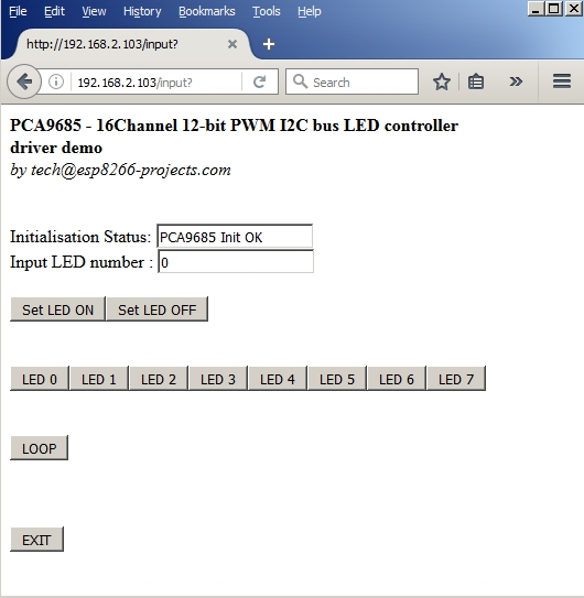
In the ESP Basic Web editor interface Type & Save your program as "PCA9685.bas" and Run it.  
If all OK the result should look as below:


Monday, November 14, 2016

Mailbag - PCF8591 I2C 8 bit ADC/DAC Driver - Part 2


ESP Basic seriesI2C driver example for the PCF8591 I2C 8-bit A/D and D/A converter - PART2

For a deeper description of the PCF8591 and simple DAC driver example please go to PART 1


 What we will need:


    Connection with the ESP8266 nEXT EVO Board is very easy, as PCF8591 Module connector is fully compatible with the nEXT Bus connector.


Driver implementation
As been a I2C compatible device you need to have a standard I2C Bus Initialisation function as usual and also to know the I2C address of the device.  
For a detailed PCF 8591 Control Byte description go to PART1.


Software: 

1. Main program: 
 
let address = 72   'PCF8591 I2C Address
i2c.setup(4,5)       'choose your I2C bus pins

cls
let dac = 0
let dac_v = 0
let adc0_1 = 0
let adc0_v = 0
let v_cal = 0.0128

adc0_1 = "ADC stopped"

wprint " <b>PCF8591 8-bit A/D and D/A converter driver demo</b><br><i>by tech@esp8266-projects.com</i><br><br> "

wprint " Input DAC value"
textbox dac

button " Set Value ",[SetDAC]

wprint " <br>DAC Output (V)"
textbox dac_v

wprint "<br>"

wprint "<br><br>ADC0 Read Value:"
textbox adc0_1

wprint "<br>ADC0 Read (Volt):"
textbox adc0_v
wprint "<br><br>"
 
button " Start ADC_0 ",[ADC0]
button " Stop ADC", [Exit ADC]

wprint "<br><br>"
button " Stop Program", [Exit]

wait


2. Set DAC subroutine: 

 [SetDAC]
dac_v = dac * v_cal

i2c.begin(address)
i2c.write(64)  'DAC Enable
delay 5
i2c.write(dac)
i2c.end()
wait


3. Enable ADC subroutine:

[ADC0]
timer 1000, [readADC]
wait


4. Read ADC subroutine:
 
[readADC]
ch = 64
i2c.begin(address)               'start another transaction
i2c.write(ch)                         'point to the ADC_0 - keep DAC ON
delay 5
i2c.end()                                'end write transaction

i2c.begin(address)                 'start another transaction
i2c.requestfrom(address,2)    'start a transaction to read 2 bytes
delay 5
adc0_0 = i2c.read()              'read the 1st byte
adc0_1 = i2c.read()              'read the 2nd byte
i2c.end()                                'end read transaction
adc0_v = v_cal + adc0_1 * v_cal
wait


5. EXIT ADC subroutine:
 
[Exit ADC]
timer 0
adc0_1 = "ADC stopped"
wait


6. Exit Program button subroutine:
 
[Exit]
timer 0
end


In the ESP Basic Web editor interface Type & Save your program as "PCF8591.bas" and Run it.  

If all OK the result should look as below:


Friday, November 11, 2016

Mailbag - PCF8591 I2C 8 bit ADC/DAC Driver - Part 1


ESP Basic series -  I2C driver example for the PCF8591 I2C 8-bit A/D and D/A converter.


General view:


   The PCF8591 is a single-chip, single-supply low-power 8-bit CMOS data acquisition
device with four analog inputs, one analog output and a serial I2C-bus interface. Three
address pins A0, A1 and A2 are used for programming the hardware address, allowing
the use of up to eight devices connected to the I2C-bus without additional hardware.
Address, control and data to and from the device are transferred serially via the two-line
bidirectional I2C-bus.
 

  The functions of the device include analog input multiplexing, on-chip track and hold
function, 8-bit analog-to-digital conversion and an 8-bit digital-to-analog conversion. The
maximum conversion rate is given by the maximum speed of the I2C-bus.


Features:

  • Single power supply
  • Operating supply voltage 2.5 V to 6.0 V
  • Low standby current
  • Serial input and output via I2C-bus
  • I2C address selection by 3 hardware address pins
  • Max sampling rate given by I2C-bus speed
  • 4 analog inputs configurable as single ended or differential inputs
  • Auto-incremented channel selection
  • Analog voltage range from VSS to VDD
  • On-chip track and hold circuit
  • 8-bit successive approximation A/D conversion
  • Multiplying DAC with one analog output.

For more details please take a look at the PCF8591 Datasheet


What we will need:

    Connection with the ESP8266 nEXT EVO Board is very easy, as PCF8591 Module connector is fully compatible with the nEXT Bus connector.


Driver implementation

As been a I2C compatible device you need to have a standard I2C Bus Initialisation function as usual and also to know the I2C address of the device.

Control Byte is the second byte sent to a PCF8591 device and is stored in its control register and is required to control the device function :


 Things to take care about: 

 The upper nibble of the control register is used for enabling the analog output, and for programming the analog inputs as single-ended or differential inputs. 
  The lower nibble selects one of the analog input channels defined by the upper nibble .

  If the auto-increment flag is set, the channel number is incremented automatically after each A/D conversion. If the auto-increment mode is desired in applications where the internal oscillator is used,
the analog output enable flag must be set in the control byte (bit 6). This allows the
internal oscillator to run continuously, by this means preventing conversion errors
resulting from oscillator start-up delay. 


  The analog output enable flag can be reset at other times to reduce quiescent power consumption.
 

   The selection of a non-existing input channel results in the highest available channel number being allocated. Therefore, if the auto-increment flag is set, the next selected channel is always channel 0. 

   The most significant bits of both nibbles are reserved for possible future functions and must be set to logic 0. After a Power-On Reset (POR) condition, all bits of the control register are reset to logic 0. 
   The D/A converter and the oscillator are disabled for power saving. 
   
  The analog output is switched to a high-impedance state.
 

Software: 

1. Main program: 
 
let address = 72 'PCF8591 I2C Address
i2c.setup(4,5) 'choose your I2C bus pins

cls
let dac = 0
let dac_v = 0
let v_cal = 0.0128

wprint " <b>PCF8591 - 8-bit A/D and D/A converter driver <br>DAC demo</b><br><i>by tech@esp8266-projects.com</i><br><br> "

wprint " Input DAC value"
textbox dac

button " Set Value ",[SetDAC]

wprint " <br>DAC Output (V)"
textbox dac_v

wprint "<br><br>"
button " Stop Program", [Exit]

wait


2. Set DAC subroutine: 

 
[SetDAC]
dac_v = dac * v_cal
i2c.begin(address)
i2c.write(64) 'Enable DAC
delay 5
i2c.write(dac)
i2c.end()
wait


3. EXIT program button:

[Exit]
timer 0
end


In the ESP Basic Web editor interface Type & Save your program as "PCF8591.bas" and Run it.  

 
If all OK the result should look as below:


If you want your program to start automatically at reboot/power ON then just Save it as "default.bas" and also from Settings Tab enable the "Run default.bas at startup".


Be aware that at start-up/reboot, it is a delay before your program will start automatically.


In  the next part about PCF8591 we will talk about the ADC Driver implementation.


Saturday, November 5, 2016

WIFI Dev Board for Home Automation - Part 2


This is Part 2 of the Wifi Dev Board for Home Automation series. For general presentation and hardware description please take a look also at Part 1 of the series


MPRSx8 Board is available also on Tindie store: https://www.tindie.com/stores/nEXT_EVO1/


What we will need:


Software implementation:

As this time we will talk about the Software side we will design a very simple driver for our board that will include also a interactive Web command interface for the MPRSx8 Home Automation Dev Board Relays.

To keep things simple, we will just add in our Web Interface 8 ON/OFF Buttons and one general OFF one, from where we can turn ON/OFF all the Relays switches. 


1. Main Program
cls                       ' clear interface
let address = 56  'PCF8574 I2C Address

i2c.setup(4,5)      'choose your I2C bus pins

i2c.begin(address)
ss = 0 xor 255      'XOR - Bit masking for the desired I/O pins
i2c.write(ss)
i2c.end()
button "x1", [5]    ' Button for Relay 1
button "x2", [6]
button "x3", [7]
button "x4", [8]
button "x5", [1]
button "x6", [2]
button "x7", [3]
button "x8", [4]    ' Button for Relay 8
button "OFF", [9] ' General OFF for all the Relays
wait


2. General OFF for all the Relays subroutine
[9]
i2c.begin(address)
ss = 0 xor 255 'XOR - Bit masking for the desired I/O pins
i2c.write(ss)
i2c.end()
wait


3. Subroutines for each Button
[1]
i2c.begin(address)
ss = ss xor 1   'XOR - Bit masking for the desired I/O pins
i2c.write(ss)
i2c.end()
wait

[2]
i2c.begin(address)
ss = ss xor 2
i2c.write(ss)
i2c.end()
wait

[3]
i2c.begin(address)
ss = ss xor 4
i2c.write(ss)
i2c.end()
wait

[4]
i2c.begin(address)
ss = ss xor 8
i2c.write(ss)
i2c.end()
wait

[5]
i2c.begin(address)
ss = ss xor 16
i2c.write(ss)
i2c.end()
wait

[6]
i2c.begin(address)
ss = ss xor 32
i2c.write(ss)
i2c.end()
wait

[7]
i2c.begin(address)
ss = ss xor 64
i2c.write(ss)
i2c.end()
wait

[8]
i2c.begin(address)
ss = ss xor 128
i2c.write(ss)
i2c.end()
wait


In the Web editor interface Save your program as "test_MPRSx8_1.bas" and Run it.


If all OK the result should look as below:


If you want your program to start automatically at reboot/power ON then just Save it as "default.bas" and also from Settings Tab enable the "Run default.bas at startup".


Be aware that at start-up/reboot, it is a delay before your program will start automatically.


WIFI MAINS 8x Relay Board for Home Automation and more


Available also on Tindie store: https://www.tindie.com/stores/nEXT_EVO1/


Features:
  • Compact, standard size: 16x5 cm! (half Eurocard height)
  • Universal AC MAINS input (240VAC/50Hz (EU) or 110V/60Hz (US)
  • Proper MOV and high quality ceramic FUSE MAINS input protection.
  • 8 x MAINS rated 15A Relays
  • 8 x independent swithing Power Channels 
  • Power Channels can be software configured for mutually exclusive usage
  • Recommended load upto 10A each channel
  • LED signaling Panel for each Power Channel Status 
  • Integrated switchmode MAINS PSU
  • Separate high efficient switchmode PSU for command & control circuit
  • Can work also from a external +12V power supply just not install the MAINS PSU
  • Safe operation design
  • I2C / nEXT Bus compatible - you can add your own extension modules - light sensors, gas, motion, etc
  • Can be stacked upto 8 boards ( 1 Master and 7 slaves) for a total of 64 Power Channels!!
  • Compatible with any I2C compatible MCU: Arduino, ARM, PIC, ATMEGA, ESP8266, ESP32, etc
  • ESP8266 friendly design: can add your ESP8266 module directly onboard for a full WIFI MAINS Power switchboard solution
  • Full access to ESP8266 pins thru 2 headers gives you even more flexibility in developing your projects!
  • Full programming header  (Tx, Rx, GPIO0 and Reset)

Command and control side - pinout details


 Schematics:


MAINS input power supply


3.3V power supply for the command and control section


Relays driver


In Part 2 we will continue with the software side, how to connect, program and use the MPRSx8 Relay board.


Creative Commons License All schematics, boards, software and articles released by ESP8266-Projects.com are licensed under a Creative Commons Attribution-NonCommercial 4.0 International License