WARNING!! You will play with LIVE MAINS!! Deadly zone!!
If you don't have any experience and are not qualified for working with MAINS power I will not ecourage you to play arround!
The story behind:
Somebody was asking few days ago on ESP8266.com forum for the easiest way to turn OFF his tube amplifier remotely. A W2MPS (Wifi Web Mains Power Switch) sounds great for this job?
The Question: How?
Because of the extensive work done before with such modules, the easiest way that I can see it to be done is a classical setup: Zero voltage crossing bilateral Triac driver + Triac combination, as a added module to our CBDB Board.

- USB adapter (take a look on Part 1 for details how to connect them together)
- Main Power Switch module (details below)
General considerations: For resistive loads ON-OFF only jobs (no dimming required) a winning combination is between MOC304X for Triac driver (Zero voltage crossing one) and a good quality Triac, decently sized by the power needs. A 25A one usually fits mostly of the needs in a domestic project, with proper heatsink for power disipation. For standard home lighting, 8A is 99% of the times more than enough for one channel. If your house is a Castle with huge chandeliers, probably not :).
Triacs are the most common used semiconductor devices for power control and switching applications. Such power control circuits can be used to remotelly switch power to electrical devices or to switch power automatically when parameters such as temperature or light intensities go beyond preset level.
BT1XX class from NXP never dissapointed. Be sure they are genuine, from a trustable source. I know, shit happens in the supply chains even to big houses from time to time but, as a good practice, a good traceability for the parts you are using is desirable.
And don't forget :LIVE MAINS Switching!!

Available models that also can be used:
BT 136 600V – 4A
BT 138 600V – 12A
BT 139 600V – 16A
BTA 23 800V – 12A
BTA 22 800V – 10A
BTA 40 800V – 40A
BTA 41 800V – 40A
A typical circuit for use when hot line switching is required:
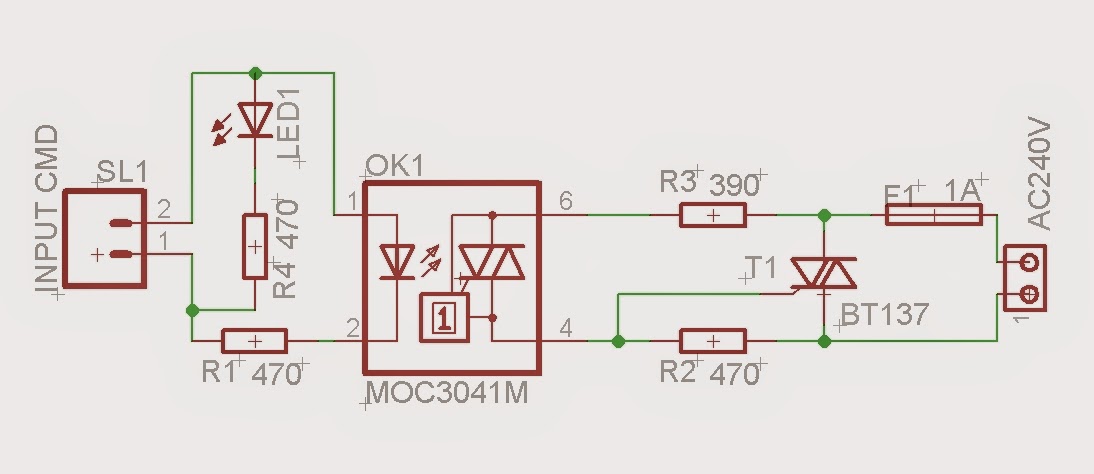 |
| MPSM schematic - 1 |
This type of circuit from above is good enough for resitive loads only. When a TRIAC controls inductive loads, the mains voltage and the load current are not in phase. To limit the slope of the reapplied voltage and ensure right TRIAC turn-off, usually is used a "snubber circuit" connected in parallel with the TRIAC. This circuit can also be used to improve TRIAC immunity to fast transient voltages.
 |
| MPSM Schematic - 2 |
The 100Ω resistor and 0.01μF capacitor are for snubbing of the triac and is often, but not always,
necessary depending upon the particular triac and load used, generally for inductive ones.
W2MPS Software
For programming CBDB Board and uploading the driver and the software we will continue to use the LuaUploader as before.
1. Define used GPIO pin:
outpin=3 -- Select IO - GPIO0
gpio.mode(outpin,gpio.OUTPUT)
gpio.write(outpin,gpio.LOW)
 |
| Connection of the CBDB Board with W2MPS Module |
W2MPS Software
For programming CBDB Board and uploading the driver and the software we will continue to use the LuaUploader as before.
1. Define used GPIO pin:
outpin=3 -- Select IO - GPIO0
gpio.mode(outpin,gpio.OUTPUT)
gpio.write(outpin,gpio.LOW)
2. Power Switch function, acting based on received command:
function PwrSW(swstat,payload)
gpio.mode(outpin,gpio.OUTPUT)
newstat=string.sub(payload,swstat[2]+1,#payload)
status = newstat
if newstat=="ON" then gpio.write(outpin,gpio.HIGH) return end
if newstat=="OFF" then gpio.write(outpin,gpio.LOW) return end
end
3. Send Page function based on request:
function sendPage(conn)
conn:send('HTTP/1.1 200 OK\n\n')
conn:send("<META HTTP-EQUIV=\"REFRESH\" CONTENT=\"5\">")
conn:send('<!DOCTYPE HTML>')
conn:send('<html>')
conn:send('<head><meta content="text/html; charset=utf-8"><style>input{width: 100px; height: 100px;}</style>')
conn:send('<title>ESP8266 - Power Switch Controller</title></head>')
conn:send('<body><h1>Power Switch Controller</h1>')
conn:send('Status: <b>')
if (status == "ON") then conn:send('<B><font color=red>ON</font></B>')
elseif (status == "OFF") then conn:send('<B><font color=green>OFF</font></B>')
else
conn:send(status)
conn:send('%')
end
conn:send('</b><br /><br />')
conn:send('<form action="/" method="POST">')
conn:send('<input type="submit" name="cmd1" value="OFF"/>')
conn:send('<input type="submit" name="cmd1" value="ON"/><br /><br /></form>')
conn:send('</body></html>')
end
4. Web Server:
srv=net.createServer(net.TCP)
srv:listen(80,function(conn)
conn:on("receive", function(conn,payload)
--next row is for debugging output only
--print(payload)
if (string.find(payload, "GET / HTTP/1.1") ~= nil) then
print("GET received")
sendPage(conn)
else
swstat={string.find(payload,"cmd1=")}
--If POST value exist, set LED power
if swstat[2]~=nil then
print("Command received: " .. payload)
PwrSW(swstat,payload)
sendPage(conn)
end
end
end)
conn:on("sent", function(conn)
conn:close()
print("Connection closed")
end)
end)
Save the code on ESP as 'web_switch.lua', restart ESP and run:
=wifi.sta.getip() -- find the IP Address where your Web Server will be
dofile("web_switch.lua") -- Start the Web Server=wifi.sta.getip() -- find the IP Address where your Web Server will be

If this is your first project with a new ESP module that was never used in your WIFI Network, don't forget to run also (one time only) :
wifi.setmode(wifi.STATION)
wifi.sta.config("<YOUR WIFI Network SSID>","<password>")
Open your favorite Web browser and type your new Web Server IP address. If all ok, should look something like below :

And a short video demonstration :
If you want the Web Power Switch software to start automatically when your CBDB module starts or reboots, then you neet to create and add some lines in your 'init.lua' file:
tmr.now() -- for debug only, you can skip it
wifi.sta.getmac() -- for debug only, you can skip it
wifi.sta.getip() -- for debug only, you can skip itnode.heap()
dofile("web_switch.lua") -- needed to start Web Server for command input
Save the code on ESP as 'init.lua', restart ESP. It should reboot and restart the program and reinitialize the Web Server:
 | |
| Step-by-step run for testing |
As I said from the beginning, this is a experimental W2MPS module example for a Web Controlled Power ON-OFF switch only. Dimming is another story, but if you are interrested about we can talk about it.
As usual, waiting your comments and suggestions. If is anybody interested I have available few of them from previous projects and can easily respin more as the parts are already available.
29 comments:
Hi, nice write up..... So, can we talk about dimming??
Thank you James. Do you need a dimmer module implementation or you are just interested on the theory behind?
Hi, I am very much looking to build a MQTT dimmer. So far I have put together this circuit http://www.instructables.com/id/Arduino-controlled-light-dimmer-The-circuit/?ALLSTEPS and was about to start trying to make it work when I came across the ESP8266 and thought that would be a much better solution. I got a simple MQTT relay working, and then found out about LUA and started investigating that. I like the way you can directly send commands so you can basically test it as you go, but I have no idea which would be the best language to use, I would be learning either way!!
Hi James, that one it's a way to do it and will work also with ESP8266 module. If I have some more time I will post also an article about AC MAINS phase control with a Triac.
It is not so trivial as it maybe looks if you want to treat it seriously. My solution might be a little more different than the one you posted but the main idea remain the same, phase control.
Keeping touch about your projects and keep an eye around :)
DISCLAIMER
I HOPE YOU ARE FULLY AWARE THAT YOU ARE IN THE DEADLY ZONE WITH MAINS!!
I will not encourage in any way any experiments with MAINS Power if you have no experience/are not qualified for something like that.
"Curiosity killed the Cat. Rumours around are about the fact she was not properly trained."
Hi thanks for the write-up, I'll be building this circuit once my vac starts to replace my Ethernet based light switch in my room. Id also be interested in a dimmer circuit/ code if you get the time.
Soon they will be some more news in the MPSW field.
A new batch of revised MPSW pcb's it's already on it's way :). After the CBDB v2 will be resealed will do my best to post also about a proper MAINS light dimmer circuit. Time it's the limited resource.
DISCLAIMER
I HOPE YOU ARE FULLY AWARE THAT YOU ARE IN THE DEADLY ZONE WITH MAINS!!
I will not encourage in any way any experiments with MAINS Power if you have no experience/knowledge/are not qualified for something like that.
CBDB v2 will be "released" not "resealed". Sleep is hunting me :D
Nice job there Tracker J, Could you share a pic of your MPSM board of the bottom side, It is exaclty what Im looking for and I want to replicate your work.
Thank you Aldo, you have the schematic used above. It is similar with the one from the MOC3041 datasheet, nothing fancy. If you are interested in a ready made one a new batch of MPSM v2 will probably arrive next 1-2 weeks. Backorder welcomed at order_at_esp8266-projects.com.
More details about MPSM v2 and CBDB v2b, next weeks :)
Please try to give add a code that will ask the SSID and password to be entered first instead of writing that in the code. I think this can be done by first making the ESP as web server ,then the HTML code is used to enter the SSID and password. Then one goes through the wireless router with the web server.
HI,
Nice Article .One of the cheapest solution to control Mains using MCU.
but have a doubt ( for resistive load)
1.Can R3 be 470 ohm
2.Can we remove R4 totally
3.What is the wattage of Resistor , 1/4W is good ?
Hi,
A kind question, have you not attached the *.lua fie of the working code or am I missing the link to the lua code file on your post?
Hi,
Why I can see the webserver working only in Chrome, when I try to see in Firefox I have a black page.
Sorry, blank page not Black page
Strange enough, example above is done in Firefox.
Hi Tracker,
Do I need to change the R2,R3 or the R7, R8 in order to work with AC120V? (Not AC240V) How do I calculate that values?
regards
Hi Jose,
I think it might work OK with the values from above, depends also on the load. If you want to have it by the book, the maximum surge current through the phototriac is determined by the maximum load voltage and the value of the resistor R8. If the maximum surge current of the phototriac Ift is 1A and we assume a 110VAC line, the value of R8 can be determined as follows: R8 = VinMAX / Ift -> R8 = 180/1 = 180ohm. I will choose a more conservative value, let's say, 220ohm. This is for a pure resistive load, in practice you can play up with the R8 value. R7 can start at 470ohm, but you can go upto 1k for your 110VAC MAINS line.
Also you need to take care of the dV/dt rating, especially for high inductive loads (all of them are more or less inductive, pure resistive loads are only in the books!).
The dV/dt rating of the triac and its driver are very important when switching inductive loads since load voltage and current are not necessary in phase. Since a triac turns off when the load current is zero, load voltage is not necessarily zero. Due to this fact, the triac may produce a sudden rise in load voltage to its own output, which may exceed its dV/dt rating. For this reason, from case to case, you need to take care of a proper snubber circuit, to protect your main triac and the phototriac.
Hi Tracker,
Thank you very much, now I understand the process to calculate the resistors, I'll find more about the snubber.
Hi, I'm trying make this project using ESP8266-01 module, but why after a minutes working the chip getting very hot to touch? is it normal? do you have any suggestion for this problem?
chip = esp8266 ? if answer is yes, no, it is not normal.
Yes esp8266, so what is the problem? Product defect?, I use 2 different esp8266-01 module with same result. :(
In your case sounds unlikely to have 2 DOA ESP modules.
I will suggest you to carefully check:
- schematic
- wiring
- power supply (must be between 3 - 3.5V / more than 250mA)
and AFTER that use a new ESP module, the 2 from above might be fried already.
Can I email you my schematic?so you can see what mistake that I made
yes, use the usual tech (at) esp8266-projects.com
omment
Sorry to bring up an old thread, I was hoping to use this circuit to control a 1HP pool pump. The pump runs on 120VAC. I saw your comments on making the changes for 120VAC, however, even with those changes how will this circuit handle 12 to 15 amps of current. I’m sure I will have to put a heat sink on the triac but will that be enough?
Thank you,
Mike
Hi Mike,
You need a bigger Triac like BTA24 (24Amps) or even bigger (bigger is better) with a proper heatsink on it. As you have there a inductive load (motor) you need also to take care at the snubber circuit/EMI filtering,etc. Using a High commutation (4 quadrant) Triac can help in this case.
Also you need proper calculated beefy traces for your MAINS circuit side, 2oz or more, with busbar or reinforcement, etc.
It's quite easy to go upto 40A, after that, things are becoming more tricky ( and way more expensive )
Happy breadboarding,
TJ.
Post a Comment