Thursday, September 29, 2016

30V Synchronous step-down DC-DC converter


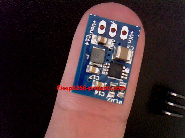
A compact breadboard friendly power module for your ESP8266, Arduino, ARM, PIC, etc project :


AVAILABE on TINDIE Store !! https://www.tindie.com/stores/nEXT_EVO1/

30V max Input, DC-DC High-Efficiency Step-down regulator, the perfect drop-in replacement for standard Linear regulators: LM7805,LM317 or similar.


And the story behind:

   I was looking for a drop-in replacement for some standard linear regulators in existing equipment that heats badly because of to small heatsinks and some poor design. Available space inside was way to small to install a bigger heatsink on most boards.

   Impressed by the results, have started using it almost everywhere where I need a good Voltage Regulator, so ended up as a standard used regulator module. If you need a nice and stable Voltage Regulator for your projects, you might found it!


  FEATURES: 
  • Up to 95% Efficiency
  • Input Voltage Range: 4.4V to 30V
  • Output Voltage Range: 2.0V to 24V (changing the divider resistor, by default comes configured for 3.3 or 5V, as you choose)
  • Output Current - 0.65A max in actual configuration - upto 1A with extra cooling.
  • Automatic Pulse Frequency Modulation/Pulse-Width Modulation (PFM/PWM) Operation
  • Low Device Shutdown Current: 3 μA typical
  • Low Device Quiescent Current: 44 μA (non-switching, PFM Mode)
  • Internal Compensation
  • Peak Current Mode Control
  • Cycle-by-Cycle Peak Current Limit
  • Undervoltage Lockout (UVLO): 4.1V typical to start 3.6V typical to stop
  • Overtemperature Protection
  • Thermal Shutdown: +150°C +25°C Hysteresis
 ...plus many more. For more details please take a look at the Datasheet.


  SCHEMATICS:


Creative Commons License
All Projects, Software, Hardware, Articles, etc released by ESP8266-Projects.com are licensed under a Creative Commons Attribution-NonCommercial 4.0 International License. 


Thursday, August 11, 2016

ESP8266 - Internal ADC 2 - the easy way example


This is just a very quick example on how to add a Voltage Divider to the ESP8266 Internal ADC input to increase the ADC input range.

For more theory behind, please take a look at the previous related article: ESP8266 - Internal ADC


Today project:

      Measure a voltage input range from 0-5V with the ESP8266 internal ADC


What do we need:

  • 2 Resistors for the voltage divider, R1=105.6k, R2=24.08k. I am using here precision resistors and the values are measured values with a proper calibrated bench meter.
  • a good, trustable, calibrated ok Multimeter.
  • some wires to connect all together.


I will not insist on connections, take a deeper look at the previous article about


Voltage divider schematic and Vout (ADC input voltage) formula


How do we do it :


1. Measure your Max desired input voltage
    In my case, Max Input Voltage (Vmax) = 5.1919 (measured)


2. Measure Resistors values:
    R1 = 105.6k
    R2 = 24.08k


3. Check if Full Scale Value at the voltage divider output is inside the ADC defined domain:
  • Calculated : Vout = (R2/(R1+R2))*Vin = 0.964072733 V
  • Measured = 0.96038V
     Good enough for the precision we are looking for. ESP8266 ADC is 10bit only and not exactly the most accurate in town


4. Calculate Voltage Divider Ratio:
  • Vdivider Ratio= Max Input Voltage/Fullscale value =  5.405976676


5.  Read ADC value : 
       adcr = adc.read(0)
      print("    ReadADC     : "..adcr)
     Average result for adcr = 1017

THIS IS IMPORTANT !! It tell us that we are inside the ADC domain as adcr < 1024 !

IF adcr > 1023 then you need to adjust your voltage divider resistors to fit inside ADC domain!


6. Calculate LSB  in 2 ways to cross check that we have the right value:
  • LSB = Input Voltage read by multimeter/ADC readed Value = 
                   =  5.1919 / 1017 =  0.005105113 V
      OR
  • LSB = (ADC Input  pin read Voltage by multimeter/ADC readed Value/)*Vdivider Ratio = 
                  = (0.96038/1017)*5.405976676 = 0.005105113 V
       It looks that we have the right LSB Value for our exercise!

     If you want to know also the ADC LSB, then
       LSB = ADC Input  pin read Voltage by multimeter/ADC readed Value  =   
                =  0.96038/1017 = 0.000944346 V

    Guess what's happening if you multiply ADC LSB with Vdivider ratio :)


7. Software Implementation for the ADC read function:

 function readADC()
      ad = 0
      LSB = 0.005105113 --calibrate based on your voltage divider AND Vref!
      adcr = adc.read(0)
      ad= adcr*LSB       
      print("    ReadADC     : "..adcr)
      print("    Read Voltage     : "..ad)
      return ad
end

and some results in the terminal window:

> SENT: readADC()
readADC()
    ReadADC     : 1017
    Read Voltage     : 5.191899921
>