Showing posts with label CBDB. Show all posts

Monday, May 18, 2015

P2 - Battery Monitor System - Web Server and data upload


 ================== W A R N I N G ! ! =================
Li-Ion batteries are very dangerous if not handled properly.
Use them only with proper protection circuits and chargers.
DO NOT OVER CHARGE / BURN / OPEN Li-Ion Bats
     Using any of the informations available on esp8266-projects.com
 is on your own risk !!
===============================================
 
    For any new CBDBv2 Evo orders/requests please feel free to use as usual:
     tech at esp8266-projects.com.
     If you want for your own experiments to order CBD v2 EVO bare PCBs only, you can also do it directly at Dirty PCBs, our preferred PCB House:
  http://dirtypcbs.com/view.php?share=5876&accesskey=3d0fd70d53d6dc20c0bf0255f67cde65
------------------------------------------------------------------------------------------------------------------


As promised, today we will continue with our Live Battery Monitor System.


Subjects of the day:
  •  WebServer interface for direct access
  •  Live Data upload over the Internet for wordwide access on Thingspeak.com.


What we will need:  

For schematics, theory of operation and technical related things please see previous article: Battery LIve Monitor System


BLMS Software
 
  For programming CBDBv2 Board and uploading the drivers and the software we will continue to use the LuaUploader as before.


1. Define used GPIO pins and variables:

ADC_SRC = 5                    -- GPIO14 - select Voltage Divider / Current Inputsda=2                                   -- GPIO4  - SDA
scl=1                                    -- GPIO5  - SCL
gpio.mode(ADC_SRC,gpio.OUTPUT, gpio.PULLUP)
gpio.write(ADC_SRC,1)      -- Voltage Measurement - Voltage Divider Source selected
gpio.write(ADC_SRC,0)      -- Current Measurement - Current Shunt Monitor output selected
voltdiv= 0.00412                -- Voltage reading calibration
dival = 0.00096                  -- ADC volt/div value - CALIBRATE !! 
resdiv = 4.31447                -- Voltage Divider Ratio - CALIBRATE!!
divalI = 0.9425                  -- Current volt/div ratio - CALIBRATE!!
cpct = 0                              -- Calculated Delivered Energy
adcI = 0                             -- ADC readings -  Curent

adcV = 0                            -- ADC readings - Voltage
pwr = 0                              -- Calculate Power
t=0                                     -- time  


2. READ ADC Process function  and calculations 

function readUI()

   gpio.write(ADC_SRC,1)
      advr=adc.read(0)
      adcV=advr*dival*resdiv
      print("\nVoltage     : " ..string.format("%g",adcV).." V")


   tmr.delay(10000)
   gpio.write(ADC_SRC,0)
      adcr=adc.read(0)
      adcI=adcr*divalI
      print("Current     : " ..string.format("%g",adcI).." mA")
   --instantaneous Power consumption calculation
   pwr = adcI*adcV
   print("Power       : " ..string.format("%g",pwr).." mW")

   -- total delivered Energy calculation
    if (adcV > 1) then
      cpct=cpct+pwr*0.002778/1000
      t = t +1
       print("Energy      : " ..string.format("%g",cpct).." W")
  else  tmr.stop(0)
        dtime = t/360         -- calculate discharge time

        print("Discharge Time: %.2fh  ",dtime)
  end
end


3. BMS WebServer

srv=net.createServer(net.TCP)
  srv:listen(80,
     function(conn)
        conn:on("receive",function(conn,payload)
        --print(payload)
        conn:send("HTTP/1.1 200 OK\n\n")
        conn:send("<META HTTP-EQUIV=\"REFRESH\" CONTENT=\"5\">")
        conn:send("<html><title>Battery Live Monitor System - ESP8266</title><body>")
        conn:send("<h1>Battery Live Monitor System - ESP8266</h1><BR>")
        conn:send("Voltage :<B><font color=red size=4>" 

                          ..string.format("%g",adcV).." V</font></b><br>")
        conn:send("Current :<B><font color=blue size=4>"

                         ..string.format("%g",adcI).." mA</font></b><br>")
        conn:send("Power   :<B><font color=red size=4>"

                        ..string.format("%g",pwr).." mW</font></b><br>")
        conn:send("Energy  :<B><font color=green size=4>"

                       ..string.format("%g",cpct).." Wh</font></b><br>")
        conn:send("<BR><BR><BR>Node.HEAP     : <b>" .. node.heap() .. "</b><BR>")
        conn:send("IP ADDR    :<b>".. wifi.sta.getip() .. "</b><BR>")
        conn:send("TMR.NOW    :<b>" .. tmr.now() .. "</b><BR<BR><BR>")
        conn:send("</html></body>")
        conn:on("sent",function(conn) conn:close() end)
        conn = nil    
      end)
end)


4. Thingspeak.com data upload  

 function sendDataTh()
    print("Sending data to thingspeak.com")
    conn=net.createConnection(net.TCP, 0)
        conn:on("receive", function(conn, payload) print(payload) end)
        conn:connect(80,'184.106.153.149')
        conn:send("GET /update?key=YOURKEYHERE&field1="..adcV.."&field2="..adcI.."&

                           field3="..pwr.."&field4="..cpct.."HTTP/1.1\r\n")
        conn:send("Host: api.thingspeak.com\r\n")
        conn:send("Accept: */*\r\n")
        conn:send("User-Agent: Mozilla/4.0 (compatible; esp8266 Lua; Windows NT 5.1)\r\n")
        conn:send("\r\n")
        conn:on("sent",function(conn) print("Closing connection")
        conn:close()
    end)
    conn:on("disconnection", function(conn) print("Got disconnection...")
    end)
end


5. MAIN program


If you have a new ESP module or is the first time when using it on a new WIFI network, don't forget to do the WIFI setup:

        -- One time ESP Setup --
        wifi.setmode(wifi.STATION)
         wifi.sta.config ( "YOUR_WIFI_SSID" , "PASSWORD" ) 
         print(wifi.sta.getip())


-- Read ADC data every 10s, print values on local Web interface and send them to thingspeak.com
 tmr.alarm(0, 10000, 1, function() readUI() sendDataTh() end)


   For testing, just save the code on ESP as 'blmsweb.lua', restart ESP and run:   
  
            dofile("blmsweb.lua")      -- Start the Battery Live Monitoring System

            print(wifi.sta.getip())       --print your BMS WebServer IP address


BLMS - First RUN

  If you want the BLMS software to start automatically when your CBDBv2 Evo Board starts or reboots, then you neet to create and add some lines in your 'init.lua' file:
  
            dofile("blmsweb.lua")      -- Start the Battery Live Monitoring System

Save the code on ESP as 'init.lua', restart ESP. It should reboot and restart automatically the program.


Open your favorite Web browser and type your new BLMS Web Server IP address. If all ok, it should look like below :

 
BLMS - Web Server interface - 20ohm Load


Thingspeak data upload

I will not insist on the Thingspeak.com account setup, it's a pretty simple process:
  1. Sign Up for a ThingSpeak account
  2. Create a new Channel by going to your Channels page and clicking Create New Channel
  3. Update your Channel via URL:
    https://api.thingspeak.com/update?api_key=YOUR_CHANNEL_API_KEY&field1=7
  4. View your Channel feed:
    https://api.thingspeak.com/channels/YOUR_CHANNEL_ID/feeds.json
Take a look at this Tutorial for more details for common devices and applications


Thingspeak.com live data uploaded - 10ohm/10W Load for stress test calibration


You can also see on graph below the moment when battery protection kicks in, around 2.4V, 2.37745 V in this case, to be more exactly:


In the video below live monitoring data, with 10 and 20ohm resistor Load:


Thursday, May 14, 2015

Battery Live Monitor System - ESP8266 CBDBv2


 ================== W A R N I N G ! ! =================
Li-Ion batteries are very dangerous if not handled properly.
Use them only with proper protection circuits and chargers.
DO NOT OVER CHARGE / BURN / OPEN Li-Ion Bats
     Using any of the informations available on esp8266-projects.com
 is on your own risk !!
===============================================


     For any new CBDBv2 Evo orders/requests please feel free to use as usual:
     tech at esp8266-projects.com.
     If you want for your own experiments to order CBD v2 EVO bare PCBs only, you can also do it directly at Dirty PCBs, our preferred PCB House:

  http://dirtypcbs.com/view.php?share=5876&accesskey=3d0fd70d53d6dc20c0bf0255f67cde65


------------------------------------------------------------------------------------------------------------------


      One of the main problem in battery powered projects is to choose/use the proper battery size/model/type. As market is flooded now with a lot of low quality batteries claiming thousands of mAh ( Ultrafire fakes stories is just an example) the only way to proper check them is to run a set of tests.
   
    A simple basic capacity test / loading / discharging time values can give you valuable informations about the parameters and health of the battery. And of course also you can see how are looking the numbers against the datasheet claims :).


  Few general considerations that I want to bring to your attention:
  • The capacity of a battery tells you how much charge it can store.  This means that they can theoretically provide a current of 2A for one hour, 1A for two hours, or 200mA for ten hours. In reality a 2,000mAh battery would not provide 20mA for 100 hours, nor 2A for one hour. 
  • Discharge load -  this is a tricky one and most of the time not clear explained by battery manufacturers in their datasheets. Mostly of them are using a discharge load of 0.1C, that means one-tenth of current capacity when rating their batteries. Therefore, a battery which can provide 200mA for 10 hours would be rated at 10x200 = 2,000mAh !!   
         A faster discharge rate would result in less energy being extracted from the battery, and
         therefore the measured capacity would be lower. If you are using batteries in energy-hungry
         devices that need more than 0.1C, the real capacity will be lower than that published.


     A "good-to-have" add-in for a battery powered project is a system that will be able to monitor over the entire battery lifetime at least few parameters like, voltage, current, power consumption and stored energy between charges. 


   What we will need:  


   Schematics:

  As the CBDBv2 Evo DevBoard has already Voltage and Current measurements capabilities onboard, the only thing that we will need to do is to connect the battery module that we want to measure to the board:


           GREEN  - V+
           BLUE    -  GND
           RED      -  SH_IN+
           WHITE -  SH_IN-


    By default the CBDBv2 Evo Board comes prepared for Li-Ion batteries voltage range, with the onboard default voltage divider values and Rshunt you have VmaxIN=4.3V and ImaxIN = 1A. If you need a different Voltage/Current range just change/ask for different default values.


CBDB v2 Evolution DevBoard with INA21x Current monitor


    The Current shunt monitor used for this project is a INA21x family one. 

    The INA210, INA211, INA212, INA213, INA214, and  INA215 are voltage-output, current-shunt monitors that can sense drops across shunts at common-mode voltages from –0.3 V to 26 V, independent of the supply voltage. 

   
    Five fixed gains are available: 50 V/V, 75 V/V, 100 V/V, 200 V/V, 500 V/V, or 1000 V/V. 
    The low offset of the zero-drift architecture enables current sensing with maximum drops across the shunt as low as 10-mV full-scale.
 

   These devices operate from a single 2.7-V to 26-V power supply, drawing a maximum of 100 μA of supply current. All versions are specified over the extended operating temperature range (–40°C to 125°C), and offered in an SC70 package. The INA210, INA213, and INA214 are also offered in a thin UQFN package.


 INA21x Features:

• Wide Common-Mode Range: –0.3 V to 26 V
• Offset Voltage: ±35 μV (Max, INA210) (Enables Shunt Drops of 10-mV Full-Scale)
• Accuracy:
– ±1% Gain Error (Max over Temperature)
– 0.5-μV/°C Offset Drift (Max)
– 10-ppm/°C Gain Drift (Max)
• Choice of Gains:
– INA210: 200 V/V
– INA211: 500 V/V
– INA212: 1000 V/V
– INA213: 50 V/V
– INA214: 100 V/V
• Quiescent Current: 100 μA (max)


     For any new CBDBv2 Evo orders/requests please feel free to use as usual: tech at esp8266-projects.com.
     If you want for your own experiments to order CBDBv2 EVO bare PCBs only, you can also do it directly at the PCB House:  

  http://dirtypcbs.com/view.php?share=5876&accesskey=3d0fd70d53d6dc20c0bf0255f67cde65


    For that ones of you that want to use a different Board or just want to add these functions to a ESP8266 Module, you just need:
  • for Voltage -  add and size on your needs the voltage divider as explained in details in the previous article about ESP8266 Internal ADC. 
  • for Current - add your favourite Current Monitor but don't forget about the VmaxIN for ESP8266 ADC of about 1V!


   BLMS Software
 
  For programming CBDBv2 Board and uploading the drivers and the software we will continue to use the LuaUploader as before.


   How to Measure Battery Capacity

   When measuring the real battery capacity what we are interested in is the amount of energy stored in a battery since it is this energy we need to power our devices. Stored energy is measured in Watt-hours - the same unit used to measure our domestic electricity consumption (where 1,000Wh = 1kWh = 1 unit of electricity).

   In order to measure the stored energy in a battery a power resistor is used as the load, and a fully charged battery is fully discharged through it. By measuring the voltage across this resistor at regular intervals during the discharge process it is simple to calcuate the total energy dissipated and therefore the total energy which had been stored in the battery.

  Using Ohm's Law (I=U/R) we can then calculate the current flowing through the load since we know the voltage across it. Instantaneous power is given by multiplying the measured voltage by the calculated current (P=U*I).

   By taking readings for a certain amount of time until the battery is completely discharged, and adding up the energy dissipated in each time interval, we can calculate the total energy taken from the battery and dissipated in the resistor and therefore the total energy that was stored in the fully charged battery.


Software Implementation
 
1. Define used GPIO pins and variables:

ADC_SRC = 5                    -- GPIO14 - select Voltage Divider / Current Inputsda=2                                   -- GPIO4  - SDA
scl=1                                    -- GPIO5  - SCL

gpio.mode(ADC_SRC,gpio.OUTPUT, gpio.PULLUP)

gpio.write(ADC_SRC,1)      -- Voltage Measurement - Voltage Divider Source selected
gpio.write(ADC_SRC,0)      -- Current Measurement - Current Shunt Monitor output selected
 

voltdiv= 0.00412                -- Voltage reading calibration
dival = 0.00096                  -- ADC volt/div value - CALIBRATE !! 
resdiv = 4.31447                -- Voltage Divider Ratio - CALIBRATE!!
divalI = 0.9425                  -- Current volt/div ratio - CALIBRATE!!
cpct = 0                              -- Calculated Delivered Energy
adcI = 0                             
-- ADC readings -  Curent

adcV = 0                            -- ADC readings - Voltage
pwr = 0                              -- Calculate Power
t=0                                     -- time 


2. READ ADC - Voltage  

function readADC_Voltage()
      adcV = 0
      advr = 0
      advr=adc.read(0)
      print("\nADCV Step   : " ..string.format("%g",advr).." steps")
      adcV=advr*dival*resdiv
      print("Voltage     : " ..string.format("%g",adcV).." V")
      return adcV
end


2. READ ADC - Current
    
function readADC_Current()
      adcI = 0
      adcr = 0
      adcr=adc.read(0)
      adcI=adcr*divalI
      print("ADCI Step   : " ..string.format("%g",adcr).." steps")
      print("Current     : " ..string.format("%g",adcI).." mA")
      return adcI
end


2. READ ADC Process function  and instantaneous Power consumtion calculation 

function readUI()
   gpio.write(ADC_SRC,1)         --select source
   adcV = readADC_Voltage()
   tmr.delay(10000)
   gpio.write(ADC_SRC,0)         
--select source
   adcI = readADC_Current()
   pwr = adcI*adcV
   print("Power       : " ..string.format("%g",pwr).." mW")
end


3. Number format function for proper LCD printing
  
nr_format = function (fnr,unit)
   if (fnr > 1000) then fnri=fnr/1000
                        uniti=string.sub(unit, 2)  
                        nrf=string.format(" %.3f%s ",fnri, uniti)
   else
   if (fnr < 100) then
                    if (fnr < 10) then
                                   nrf = string.format("  %.1f%s ",fnr, unit)
                      else nrf = string.format(" %.1f%s ",fnr,unit)
                    end
    else nrf = string.format("%.1f%s ",fnr,unit)
   end
  end   
   return nrf
end


4. LCD Print - > Voltage / Current / Energy / Power

    For more details about the I2C LCD Driver , please take a look at the ST7032i LCD Driver Article
 

LCDout = function()
   if (t==0) then st7032i:lcd_clear() end
   if (adcV > 1) then
      st7032i:lcd_print(1,1,string.format("%.3fV",adcV))
      adci = nr_format(adcI,"mA")
      st7032i:lcd_print(8,1,adci) 
      pwrp = nr_format(pwr,"mW")
      st7032i:lcd_print(0,2,pwrp)
      cpct=cpct+pwr*0.002778 --every 10 sec readings
      cpctp = nr_format(cpct,"mWh")
      t = t +1
      st7032i:lcd_print(8,2,cpctp)
  else  tmr.stop(0)
        dtime = t/360
        st7032i:lcd_print(0,1,string.format("Disc.Time:%.2fh ",dtime))
        st7032i:lcd_print(0,2,"Energy: ")
  end
end  


5. MAIN program

require('st7032i')
st7032i:init_i2c(sda,scl)
st7032i:init_LCD()
st7032i:lcd_clear()
st7032i:lcd_print(1,1,string.format("Battery Monitor"))
st7032i:lcd_print(3,2,string.format("Starting ..."))
 

tmr.alarm(0, 10000, 1, function() readUI() LCDout() tmr.delay(1000) end)


   For testing, just save the code on ESP as 'blms.lua', restart ESP and run:   
  

            dofile("blms.lua")      -- Start the Battery Live Monitoring System


Running BLMS program


    If you want the BLMS software to start automatically when your CBDB module starts or reboots, then you neet to create and add some lines in your 'init.lua' file:
  
            dofile("blms.lua")      -- Start the Battery Live Monitoring System

Save the code on ESP as 'init.lua', restart ESP. It should reboot and restart automatically the program.


That's all for today, next time we will continue with Web Interface and online logging system for the BLMS!


Monday, April 27, 2015

P2 - ESP8266 Ultimate DevBoard - Firmware upload and first run


  Part 2 of the the new CBDBv2 Evolution Series


  Let's begin our today story with a quick remember of the CBDBv2 DevBoard features:


    Finished Board with headers and some EXT modules in place:

CBDB Evolution - bottom view

EXT Modules


CBDB Evolution - top view

   First thing to see is how easy is the process to configure and start using CBCBv2 (code name Evolution) Board. It will come preconfigured with NodeMCU, so, if LUA is your desired programming language you can just start using it.

   In case of firmware update needed or if you want to change the environment, it is a very easy process, similar with the one used for MPSM Board.


   What we will need:


Uploading  new firmware:


1. Using the clasic "jumper-style" procedure

  • connect CBDB Module with the USB Adapter (Tx, Rx, 3v3, GND), Set the PROG jumper in the Programming mode position (closed) and power on

CBDBv2 - Firmware Programming mode enabled

  • Start NodeMCU Flasher. Choose you USB adapter corresponding port
  • Add from Config Menu latest previously downloaded firmware. It must start from 0x0000. Disable anything else. 
  • Go back on Operation tab. Power off your CBDB Module. Press FLASH Button. power ON quick CBDB module. It will be recognised and will start flashing. Give it a second try if necessary.
  •  When finished succesfully A green OK checkmark will appear
  •  Power Off CBDB Module, Remove yellow jumper. Power back ON. Your CBDBv2 Board should be now programmed with the new NodeMCU Firmware.


    If you change very often the firmware or want a easier way to use CBDBv2 DevBoard with Arduino IDE or direct GCC/Eclipse programming then maybe you will prefer the second available procedure for uploading your firmware:


2. Using the Auto reset/bootloading mode:

   Another great tool for uploading new firmware for your CBDBv2 DevBoard is esptool.
I want to thank you themadinventor for such a great utility program and also want to thank for the received improvements from several members of the ESP8266 community, including pfalcon, tommie, 0ff and george-hopkins. Great job!

   We will use in this example the CK version (thank you Christian) but any version of esptool that is supporting the RTS/DTR reset/bootloading mode must work ok. If you want to avoid compiling yourself the program you can download the binary file from here:  esptool-bin.zip


    Upload procedure:
  • connect CBDB Module with the USB Adapter (Tx, Rx, RTS, DTR, 3v3, GND) and power on
Auto reset/bootloading mode configuration


  • In Command Prompt Start esptool.exe program:
         D:\ESPTool>esptool.exe -cp COM34 -cd ck -cf nodemcu_latest.bin

          cp  - Select the serial port device to use for communicating with the ESP.
          cd  - Select the reset method to use for resetting the board.
          cf  - Select the firmware file that you want to flash memory


   For further programming in LUA, it might be possible to do it directly in your Serial Terminal Program but I will recomend you to use a more dedicated program for that, like LuaLoader or LuaUploader. I will stay with the latest one, for it's great flexibility and simplicity.

   To run a quick test, you can just use the code snippets provided by LuaUploader at start-up. Select the piece of code that you want to run and press "Execute Selection" button.

  • To quick setup your WIFI network :
        -- One time ESP Setup --
        wifi.setmode(wifi.STATION)
         wifi.sta.config ( "YOUR_WIFI_SSID" , "PASSWORD" ) 
         print(wifi.sta.getip())


  • For the Blinky test, just use a prepared LED as in the picture, insert it on previously used yellow jumper place (GPIO0) and run the code from below
Be careful with Anode / catode orientation

                -- Blink using timer alarm --
                timerId = 0 -- we have seven timers! 0..6
                dly = 500 -- milliseconds
                ledPin = 3 -- 3=GPIO0
                gpio.mode(ledPin,gpio.OUTPUT)
               ledState = 0
               tmr.alarm( timerId, dly, 1, function()
                  ledState = 1 - ledState;
                  gpio.write(ledPin, ledState)
               end)


UPDATE !! UPDATE !! UPDATE !!


Yes, it's true.

For all the Arduino IDE lovers:

Arduino IDE first test for direct programming and firmware uploading on the new ESP8266 CBDBv2 Evolution DevBoard. No manual reset needed , no buttons to press, just press Upload and that's it!

 Running Blinky LED program on GPIO15:

// the setup function runs once when you press reset or power the board
void setup() {
     // initialize digital pin 15 as an output.
     pinMode(15, OUTPUT);
}

// the loop function runs over and over again forever
void loop() {
     digitalWrite(15, HIGH);   // turn the LED on (HIGH is the voltage level)
     delay(500);              // wait for a second
     digitalWrite(15, LOW);    // turn the LED off by making the voltage LOW
     delay(500);              // wait for a second
}


Friday, April 24, 2015

ESP8266 Ultimate DevBoard - Finally Arrived!!


   What do you really expect from a IOT Development board?

   I'm sure most of you will say easy configurable Internet access. Direct Wifi if possible.

   And after that?

   What do you think do you need mostly for your IOT Projects?

   Maybe some sort of easy interaction and data exchange with the real world environment?


  Sounds intriguing to start with so many questions but they are more than legitimate:

  When removing all the bells and whistles, what do we REALLY need to develop the next level of IOT devices?


    If you asked yourself already all these questions, and I'm sure a lot of you has done it already, thinking on your own future projects, what do you think about a IOT Development Board that can offer you at least:


   Sounds good? sounds impossible? Well...I hope that I have, at least for a part of you, one of the right answers below:

CBDB v2 Schematic


  A DevBoard full of functions in a 5x5 size PCB, small enough to easy integrate in your hobbyist workplace ecosystem :)


CBDB V2 DevBoard PCB - TOP


   Latest design review PCBs of the fresh new ESP8266 Dev Board v.2 just landed on my desk and is definitely a next step in Experimenting in the IOT world. Designed with ease of use and flexibility in mind it will offer you endless hours of Experimenting, Programming and Developing your own projects.


     For any new requests please feel free to use as usual: tech at esp8266-projects.com.
     If you want for your own experiments to order CBD v2 EVO bare PCBs only, you can also do it directly at Dirty PCBs, our preferred PCB House:
  http://dirtypcbs.com/view.php?share=5876&accesskey=3d0fd70d53d6dc20c0bf0255f67cde65

     Please keep in mind this is a experimental board, not a commercial product and is offered as it is. If it will burn your house, help the Aliens to abduct you or even eat your cat it's your problem not mine. The old enough ones to remember ALF will understand even deeper the disclaimer :)


  On the TOP side, you can easily directly integrate your LCD or if you want it separate just run it thru a usual cable:
 
CBDB v2 - TOP


     After finished soldering, cleaning and cooling down, this is how is looking the ESP8266 CBDBv2 DevBoard ready for testing  the onboard regulator :


Testing was done with power supplied from a Li-Ion Battery pack and also from a standard 5V SMPS unit under a decent 500mA load. No overheating or nasty oscillations, looks good up to 800mA. Are 800mA warm but the proper calculated double side heatsink area is doing the job right :).


Onboard regulator test - 5V  SMPS Supply


    I know it's a big debate this days about 1A requirement for ESP8266 Modules, but from all my experience and informations, at least with the ESP-07/12 Modules I had in my hands in the latest months, they were never exceed the 250mA margin. In fact, I have one module running for months now as a temperature logger/webserver and the power consumption looks constantly as in the pictures below:

Full drain test with thinkspeak data upload and 1/s direct web access reload


Temperature  Logger supply line monitoring


   I must also admit that I have also some old ESP-01 Modules, never used them, they are indeed looking very power hungry but never had the time to check them how much power they require to properly operate. Or if they are just faulty.

   I have seen before entire batches of faulty ESP8266 modules. Even ESP-07 ones if you remember the story. What I can confirm about these ESP-01 modules is that they cannot be programmed using power directly from my CP2102 USB Adapter, as ESP-07/12. Not enough juice for them. Why? If I will find some time will take a look at them. If is anybody out there that has the answer, please share it with us.


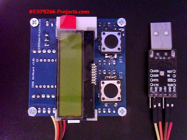
And finally, this is how is looking, ready for firmware upload and first tests:
 ESP8266 DevBoard

Stay tuned for what will follow soon:  firmware uploading and the infamous Blinky test:)