Showing posts with label battery. Show all posts

Wednesday, May 27, 2015

Raspberry PI - Standalone Thingspeak Server installation


UPDATE !! UPDATE !! UPDATE !! UPDATE !!

New fresh install instructions based on the new RASPBIAN Jessie: Raspberry PI2 + Thingspeak Server on RASPBIAN Jessie

-------------------------------------------------------------------------------------------------

Original Article

     As you might read already in my previous  ESP8266 Battery Monitor System  post I was using Thingspeak.com, because of it's flexibility, as a logger for live data uploading.
In the latest week I was exploring deeper Thigspeak capabilities.

   As you know, Thinspeak.com it's a open source project, and you have full access to the project sources on Github 

   What I was interested for was to check the possibility to build/configure and use a standalone Thingspeak Server that can run independently of Internet infrastructure on a small footprint, low power consumption platform.
   The interesting part regarding the Thingspeak Server deployment is the chosen platform, the new RASPBERRY PI 2 Board!
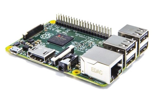


    I will present you below the step-by-step process to install your own RPI Thingspeak Server that can be tailored on your own needs and ofcourse, not affected by Internet connection availability and uptime if installed in the same physical location/LAN as your ESP8266 BMS or any sensor grid/array you might want to use with!


INSTALLATION PROCESS:


1.  Install a Raspberry Pi Operating System image on SD card

  •  Download the Raspbian image from RPI website
  •  Write image to SDCard
    For more details please read RPI Install Guide

I was using the Win32DiskImager utility under W7Pro for that, worked like a charm.


2. First RPI RUN with the new SDCard:


  • Inset card in RPI2
  • Boot 
  • From raspi-config:
              - Set to use entire SDcard space
              - Set hostname: RPIMON1
              - Enable SSH Server
              - Write down your new RPI IP: 192.168.2.xx

  • Reboot for apply new hostname & settings
                pi@RPIMON1~$ sudo reboot


3. System Update & required packages install
  • Switch over to SSH remote access with Putty - accept new key


  • Change "pi" account password:
                  pi@RPIMON1~$passwd
  • Set ROOT password, so you can then use root (just for very, very special things!)
              pi@RPIMON1~$sudo passwd root

  • System Update & upgrade  :
              pi@RPIMON1~$sudo apt-get update            
              pi@RPIMON1~$sudo apt-get upgrade          
              pi@RPIMON1~$sudo apt-get dist-upgrade   
              pi@RPIMON1~$sudo sync

  • Reboot:
            pi@RPIMON1~$ sudo reboot


  • Required packages:
           pi@RPIMON1~$sudo apt-get -y install build-essential git mysql-server mysql-client 
                                       libmysqlclient-dev libxml2-dev libxslt-dev libssl-dev libsqlite3-dev


4.  MySQL Database configuration


pi@RPIMON1~$mysql --user=root mysql -p useyourpasswd here
pi@RPIMON1~$mysql> CREATE USER 'thing'@'localhost' IDENTIFIED BY 'speak’;
pi@RPIMON1~$mysql> GRANT ALL PRIVILEGES ON *.* TO 'thing'@'localhost' WITH GRANT OPTION;
pi@RPIMON1~$mysql> commit;
pi@RPIMON1~$mysql> exit;


5.  Ruby & Rails install

          pi@RPIMON1~$wget http://cache.ruby-lang.org/pub/ruby/2.1/ruby-2.1.5.tar.gz
          pi@RPIMON1~$tar xvzf ruby-2.1.5.tar.gz
          pi@RPIMON1~$cd ruby-2.1.5
          pi@RPIMON1~$./configure
          pi@RPIMON1~$make
          pi@RPIMON1~$sudo make install
          pi@RPIMON1~$cd ..
          pi@RPIMON1~$echo "gem: --no-rdoc --no-ri" >> ${HOME}/.gemrc
          pi@RPIMON1~$sudo gem install rails


 6.  THINGSPEAK SERVER INSTALL

pi@RPIMON1~$git clone https://github.com/iobridge/thingspeak.git
pi@RPIMON1~$cp thingspeak/config/database.yml.example thingspeak/config/database.yml
pi@RPIMON1~$cd thingspeak
pi@RPIMON1~$bundle install
pi@RPIMON1~$bundle exec rake db:create

pi@RPIMON1~$mysql --user=root mysql -p
pi@RPIMON1~$mysql> show databases;
pi@RPIMON1~$mysql> exit;


IF all OK continue with loading Thingspeak DB configuration

pi@RPIMON1~$bundle exec rake db:schema:load


RUN the THINGSPEAK SERVER:

pi@RPIMON1 ~/yourthingspeak $ rails server webrick


And the result in Browser:

Running Thingspeak on RPI Board

Create new Thingspeak USER:

Thingspeak Signup page


Create new CHANNEL

Create new channel for ESP8266 BMS data upload


Live Data update:

ESP8266 BMS  - Live data upload


UPDATE !! UPDATE !! UPDATE !! UPDATE !!

New fresh install instructions based on the new RASPBIAN Jessie: Raspberry PI2 + Thingspeak Server on RASPBIAN Jessie


Thursday, May 14, 2015

Battery Live Monitor System - ESP8266 CBDBv2


 ================== W A R N I N G ! ! =================
Li-Ion batteries are very dangerous if not handled properly.
Use them only with proper protection circuits and chargers.
DO NOT OVER CHARGE / BURN / OPEN Li-Ion Bats
     Using any of the informations available on esp8266-projects.com
 is on your own risk !!
===============================================


     For any new CBDBv2 Evo orders/requests please feel free to use as usual:
     tech at esp8266-projects.com.
     If you want for your own experiments to order CBD v2 EVO bare PCBs only, you can also do it directly at Dirty PCBs, our preferred PCB House:

  http://dirtypcbs.com/view.php?share=5876&accesskey=3d0fd70d53d6dc20c0bf0255f67cde65


------------------------------------------------------------------------------------------------------------------


      One of the main problem in battery powered projects is to choose/use the proper battery size/model/type. As market is flooded now with a lot of low quality batteries claiming thousands of mAh ( Ultrafire fakes stories is just an example) the only way to proper check them is to run a set of tests.
   
    A simple basic capacity test / loading / discharging time values can give you valuable informations about the parameters and health of the battery. And of course also you can see how are looking the numbers against the datasheet claims :).


  Few general considerations that I want to bring to your attention:
  • The capacity of a battery tells you how much charge it can store.  This means that they can theoretically provide a current of 2A for one hour, 1A for two hours, or 200mA for ten hours. In reality a 2,000mAh battery would not provide 20mA for 100 hours, nor 2A for one hour. 
  • Discharge load -  this is a tricky one and most of the time not clear explained by battery manufacturers in their datasheets. Mostly of them are using a discharge load of 0.1C, that means one-tenth of current capacity when rating their batteries. Therefore, a battery which can provide 200mA for 10 hours would be rated at 10x200 = 2,000mAh !!   
         A faster discharge rate would result in less energy being extracted from the battery, and
         therefore the measured capacity would be lower. If you are using batteries in energy-hungry
         devices that need more than 0.1C, the real capacity will be lower than that published.


     A "good-to-have" add-in for a battery powered project is a system that will be able to monitor over the entire battery lifetime at least few parameters like, voltage, current, power consumption and stored energy between charges. 


   What we will need:  


   Schematics:

  As the CBDBv2 Evo DevBoard has already Voltage and Current measurements capabilities onboard, the only thing that we will need to do is to connect the battery module that we want to measure to the board:


           GREEN  - V+
           BLUE    -  GND
           RED      -  SH_IN+
           WHITE -  SH_IN-


    By default the CBDBv2 Evo Board comes prepared for Li-Ion batteries voltage range, with the onboard default voltage divider values and Rshunt you have VmaxIN=4.3V and ImaxIN = 1A. If you need a different Voltage/Current range just change/ask for different default values.


CBDB v2 Evolution DevBoard with INA21x Current monitor


    The Current shunt monitor used for this project is a INA21x family one. 

    The INA210, INA211, INA212, INA213, INA214, and  INA215 are voltage-output, current-shunt monitors that can sense drops across shunts at common-mode voltages from –0.3 V to 26 V, independent of the supply voltage. 

   
    Five fixed gains are available: 50 V/V, 75 V/V, 100 V/V, 200 V/V, 500 V/V, or 1000 V/V. 
    The low offset of the zero-drift architecture enables current sensing with maximum drops across the shunt as low as 10-mV full-scale.
 

   These devices operate from a single 2.7-V to 26-V power supply, drawing a maximum of 100 μA of supply current. All versions are specified over the extended operating temperature range (–40°C to 125°C), and offered in an SC70 package. The INA210, INA213, and INA214 are also offered in a thin UQFN package.


 INA21x Features:

• Wide Common-Mode Range: –0.3 V to 26 V
• Offset Voltage: ±35 μV (Max, INA210) (Enables Shunt Drops of 10-mV Full-Scale)
• Accuracy:
– ±1% Gain Error (Max over Temperature)
– 0.5-μV/°C Offset Drift (Max)
– 10-ppm/°C Gain Drift (Max)
• Choice of Gains:
– INA210: 200 V/V
– INA211: 500 V/V
– INA212: 1000 V/V
– INA213: 50 V/V
– INA214: 100 V/V
• Quiescent Current: 100 μA (max)


     For any new CBDBv2 Evo orders/requests please feel free to use as usual: tech at esp8266-projects.com.
     If you want for your own experiments to order CBDBv2 EVO bare PCBs only, you can also do it directly at the PCB House:  

  http://dirtypcbs.com/view.php?share=5876&accesskey=3d0fd70d53d6dc20c0bf0255f67cde65


    For that ones of you that want to use a different Board or just want to add these functions to a ESP8266 Module, you just need:
  • for Voltage -  add and size on your needs the voltage divider as explained in details in the previous article about ESP8266 Internal ADC. 
  • for Current - add your favourite Current Monitor but don't forget about the VmaxIN for ESP8266 ADC of about 1V!


   BLMS Software
 
  For programming CBDBv2 Board and uploading the drivers and the software we will continue to use the LuaUploader as before.


   How to Measure Battery Capacity

   When measuring the real battery capacity what we are interested in is the amount of energy stored in a battery since it is this energy we need to power our devices. Stored energy is measured in Watt-hours - the same unit used to measure our domestic electricity consumption (where 1,000Wh = 1kWh = 1 unit of electricity).

   In order to measure the stored energy in a battery a power resistor is used as the load, and a fully charged battery is fully discharged through it. By measuring the voltage across this resistor at regular intervals during the discharge process it is simple to calcuate the total energy dissipated and therefore the total energy which had been stored in the battery.

  Using Ohm's Law (I=U/R) we can then calculate the current flowing through the load since we know the voltage across it. Instantaneous power is given by multiplying the measured voltage by the calculated current (P=U*I).

   By taking readings for a certain amount of time until the battery is completely discharged, and adding up the energy dissipated in each time interval, we can calculate the total energy taken from the battery and dissipated in the resistor and therefore the total energy that was stored in the fully charged battery.


Software Implementation
 
1. Define used GPIO pins and variables:

ADC_SRC = 5                    -- GPIO14 - select Voltage Divider / Current Inputsda=2                                   -- GPIO4  - SDA
scl=1                                    -- GPIO5  - SCL

gpio.mode(ADC_SRC,gpio.OUTPUT, gpio.PULLUP)

gpio.write(ADC_SRC,1)      -- Voltage Measurement - Voltage Divider Source selected
gpio.write(ADC_SRC,0)      -- Current Measurement - Current Shunt Monitor output selected
 

voltdiv= 0.00412                -- Voltage reading calibration
dival = 0.00096                  -- ADC volt/div value - CALIBRATE !! 
resdiv = 4.31447                -- Voltage Divider Ratio - CALIBRATE!!
divalI = 0.9425                  -- Current volt/div ratio - CALIBRATE!!
cpct = 0                              -- Calculated Delivered Energy
adcI = 0                             
-- ADC readings -  Curent

adcV = 0                            -- ADC readings - Voltage
pwr = 0                              -- Calculate Power
t=0                                     -- time 


2. READ ADC - Voltage  

function readADC_Voltage()
      adcV = 0
      advr = 0
      advr=adc.read(0)
      print("\nADCV Step   : " ..string.format("%g",advr).." steps")
      adcV=advr*dival*resdiv
      print("Voltage     : " ..string.format("%g",adcV).." V")
      return adcV
end


2. READ ADC - Current
    
function readADC_Current()
      adcI = 0
      adcr = 0
      adcr=adc.read(0)
      adcI=adcr*divalI
      print("ADCI Step   : " ..string.format("%g",adcr).." steps")
      print("Current     : " ..string.format("%g",adcI).." mA")
      return adcI
end


2. READ ADC Process function  and instantaneous Power consumtion calculation 

function readUI()
   gpio.write(ADC_SRC,1)         --select source
   adcV = readADC_Voltage()
   tmr.delay(10000)
   gpio.write(ADC_SRC,0)         
--select source
   adcI = readADC_Current()
   pwr = adcI*adcV
   print("Power       : " ..string.format("%g",pwr).." mW")
end


3. Number format function for proper LCD printing
  
nr_format = function (fnr,unit)
   if (fnr > 1000) then fnri=fnr/1000
                        uniti=string.sub(unit, 2)  
                        nrf=string.format(" %.3f%s ",fnri, uniti)
   else
   if (fnr < 100) then
                    if (fnr < 10) then
                                   nrf = string.format("  %.1f%s ",fnr, unit)
                      else nrf = string.format(" %.1f%s ",fnr,unit)
                    end
    else nrf = string.format("%.1f%s ",fnr,unit)
   end
  end   
   return nrf
end


4. LCD Print - > Voltage / Current / Energy / Power

    For more details about the I2C LCD Driver , please take a look at the ST7032i LCD Driver Article
 

LCDout = function()
   if (t==0) then st7032i:lcd_clear() end
   if (adcV > 1) then
      st7032i:lcd_print(1,1,string.format("%.3fV",adcV))
      adci = nr_format(adcI,"mA")
      st7032i:lcd_print(8,1,adci) 
      pwrp = nr_format(pwr,"mW")
      st7032i:lcd_print(0,2,pwrp)
      cpct=cpct+pwr*0.002778 --every 10 sec readings
      cpctp = nr_format(cpct,"mWh")
      t = t +1
      st7032i:lcd_print(8,2,cpctp)
  else  tmr.stop(0)
        dtime = t/360
        st7032i:lcd_print(0,1,string.format("Disc.Time:%.2fh ",dtime))
        st7032i:lcd_print(0,2,"Energy: ")
  end
end  


5. MAIN program

require('st7032i')
st7032i:init_i2c(sda,scl)
st7032i:init_LCD()
st7032i:lcd_clear()
st7032i:lcd_print(1,1,string.format("Battery Monitor"))
st7032i:lcd_print(3,2,string.format("Starting ..."))
 

tmr.alarm(0, 10000, 1, function() readUI() LCDout() tmr.delay(1000) end)


   For testing, just save the code on ESP as 'blms.lua', restart ESP and run:   
  

            dofile("blms.lua")      -- Start the Battery Live Monitoring System


Running BLMS program


    If you want the BLMS software to start automatically when your CBDB module starts or reboots, then you neet to create and add some lines in your 'init.lua' file:
  
            dofile("blms.lua")      -- Start the Battery Live Monitoring System

Save the code on ESP as 'init.lua', restart ESP. It should reboot and restart automatically the program.


That's all for today, next time we will continue with Web Interface and online logging system for the BLMS!


Monday, March 16, 2015

Mailbag arrival! New Battery solution for ESP8266 Modules!

================== W A R N I N G ! ! =================
Li-Ion batteries are very dangerous if not handled properly.
Use them only with proper protection circuits and chargers.
DO NOT OVER CHARGE / BURN / OPEN Li-Ion Bats
     Using any of the informations available on esp8266-projects.com
 is on your own risk !!
===============================================


   Finally Arrived! This was a long awaited one. Postal service at it's best :)

   I was asked for a more compact and easy to recharge battery pack solution for the ESP8266 Modules and with the new items arrived in the MailBox, here it is:


ESP8266 Battery Module

What we will need:
  • LGDB318650 - Rechargeable 3,7V/2600mAh Li-ion Cell 
  • 18650 Cell holder
  • Li-ion Charger/Monitor with protection
  • Asorted wires - choose your desired color but red/black, blue/white standard coding with be better :)

Li-ion Cell and holder
   As the LGDS318650 Li-ion Cells does not have any internal protection been bare ones - usual find in laptops battery packs - we will need to use a charger/monitor with some sort of protection mechanism.

Forget the Ni-Mh abuse if you want to run your Li-ion cells properly and safely for a long lifespan.  Li-ion Cells shouldn't be charged/discharged/drained more than the recommended values to prolong its life and even to avoid a nasty explosion or fire!


The module from the picture below it's covering decently all the required needs:
  • USB compatible constant-current/constant-voltage charger - linear
  • Monitor for overcharge/overdischarge and/or overcurrent
  • High speed MOSFET Switching protection mechanism
 
Li-ion Cell Charger/Monitor with protection


   It is based on TP4056 1A Standalone Linear Li-lon Battery Charger with Thermal Regulation chip

   The TP4056 is a complete constant-current/constant-voltage linear charger for single cell
lithium-ion batteries. Its SOP package and low external component count make the TP4056
ideally suited for portable applications. Furthermore, the TP4056 can work within USB and wall
adapter.

   No blocking diode is required due to the internal PMOSFET architecture and have prevent to
negative Charge Current Circuit. Thermal feedback regulates the charge current to limit the die
temperature during high power operation or high ambient temperature. The charge voltage is
fixed at 4.2V, and the charge current can be programmed externally with a single resistor. The
TP4056 automatically terminates the charge cycle when the charge current drops to 1/10th the
programmed value after the final float voltage is reached.

    TP4056 Other features include current monitor, under voltage lockout, automatic recharge and
two status pin to indicate charge termination and the presence of an input voltage.
 
TP4056 - SO8 package

  
 FEATURES:

  •  Programmable Charge Current Up to  1000mA 
  • No MOSFET, Sense Resistor or Blocking  Diode Required
  • Complete Linear Charger in SOP-8 Package for Single Cell Lithium-Ion Batteries
  • Constant-Current/Constant-Voltage
  • Charges Single Cell Li-Ion Batteries Directly from USB Port
  • Preset 4.2V Charge Voltage with 1.5% Accuracy
  • Automatic Recharge
  • Two Charge Status Output Pins
  • C/10 Charge Termination
  • 2.9V Trickle Charge Threshold (TP4056) 
  • Soft-Start Limits Inrush Current
   For more details please see TP4056 Datasheet

   TP4056 is accompanied with DW01-G battery protection IC.

   DW01-G is designed to protect lithium-ion/polymer battery from damage or degrading the lifetime due to overcharge,overdischarge, and/or overcurrent for one-cell lithium-ion/polymer battery powered systems, such as cellular phones.

Protection circuit - DW01-G + Mosfet switch
   DW01-G has an accuracy of ±50mV overcharging detection voltage that ensures safe and full utilization charging. Also the very low standby current drains little current from the cell while in storage.

FEATURES:
  • Reduction in Board Size due to Miniature SOT-23-6 Package
  • Ultra-Low Quiescent Current at 3μA (Vcc=3.9V)
  • Ultra-Low Power-Down Current at 0.1μA (Vcc=2.0V)
  • Precision Overcharge Protection Voltage 4.25V ± 50mV
  • Load Detection Function during Overcharge Mode
  • Two Detection Levels for Overcurrent Protection
  • Delay times are generated by internal circuits. No external capacitors required
  Battery Protection Swithing is done with 8205A Mosfet. The ML8205A uses advanced trench technology to provide excellent RDS(ON), low gate charge and operation with gate voltages as low as 2.5V. This device is suitable for use as a Battery protection or in other Switching application.

We will use this battery solution setup in the future for our battery powered projects.

Stay tuned for more about soon!